 Skip to content
Horn antenna is a widely used microwave antenna. It features a simple structure, broadband, high gain and high efficiency. It’s widely used for antenna measurement, wireless communication, satellite communication, radar system, high-resolution imaging, and Enhanced Ultra High Throughput (EUHT) Wireless Communication System.
Horn antennas are of different types that give you a variety to choose from. The choice would depend on the need and function that the antenna has to perform. Following are 9 main types of horn antennas that will help you understand their different features and determine which one you need. These 8 categories are not absolutely accurate, some categories are just different names or aliases, but the function is the same.
Rule of Thumb for Approximating the Horn Antenna Pattern
A simple guideline for estimating the radiation pattern of a horn antenna is to remember that the power drops off rapidly away from the main beam. Specifically, the power decreases by about 10 dB at the angle where the pattern’s intensity falls to one-tenth its peak value. This “-10 dB point” helps you visualize how tightly focused or broad your horn antenna’s main lobe will be.
In most practical cases, the pattern is roughly symmetrical and follows a Gaussian-like shape. For a quick approximation, you can consider that outside the -10 dB beamwidth, the signal strength tapers off significantly—making the antenna highly directional and ideal for applications where precise targeting is important.
Materials Used for Dielectric Plates in Horn Antennas
When it comes to dielectric plates in horn antennas, material selection is crucial to performance. Typically, these plates are crafted from materials that offer low loss at the antenna’s operating frequencies. One of the most common choices is PTFE (Polytetrafluoroethylene), known commercially as Teflon™, thanks to its excellent dielectric properties and minimal signal attenuation.
The reason PTFE and similar materials are favored is twofold:
- Low Dielectric Loss: This ensures minimal signal degradation as the wave propagates through the plate.
- Consistency and Stability: PTFE maintains its electrical and mechanical characteristics even at high frequencies, making it reliable for applications that demand precision.
In essence, the right dielectric material ensures that the plate can effectively introduce the desired phase shift to the wave—often 45º between axes—to enable polarization control, such as generating circular polarization. This process hinges on the plate’s specific shape, size, and dielectric constant, so manufacturers prioritize materials like PTFE for both their performance and reliability.
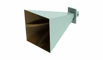
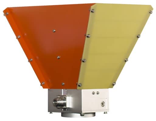
What is the Asymmetrical Horn antenna?
One side gradually opens outward, and the other side is parallel to the waveguide plane with a rectangular opening called an asymmetric horn antenna. It can also be named an H-plane sector antenna or an E-plane sector antenna.
Sanny Telecom Asymmetrical horn antenna series operates from 5150MHz to 6500MHz with optional gain and half-power beamwidth. It also supports WiFi 7 band 5925-7125MHz with a new alternative feedhorn.
Features:
- Wideband, high gain
- Dual polarization
- N-female connectors
- High isolation& F/B ratio
- Extremely low sidelobe
- Asymmetrical beam shape
- N-female connectors
- Optional frequency range, gain, beamwidth
Applications:
What is Broadband Horn Antenna?
A horn antenna operates at 0.1-50GHz with 4-15 gain, and linear polarization is a broadband horn antenna.The broadband horn antenna can be used for transmitting or receiving wireless signal. It also includes the double ridge horn antenna or dual ridged horn antenna.
Features:
- Compact and lightweight design
- High gain, low VSWR
- Extremely wide bands
- Linear polarization
- Optional frequency ranges, gain
Applications:
- Antenna Measurement
- EMC/RF Measurement
- Surveillance System
- Radar Detection System
What is Conical Horn Antenna?
A horn antenna has a circular or rectangular waveguide interface with linear or circular polarization and conical cross-section, called a conical horn antenna. The frequency range is from 17.5GHz to 170GHz, with a standard gain of 14dBi to 25dBi and a maximum VSWR of 1.15:1.
The circular waveguide interface can support multiple polarization types, including horizontal polarization, vertical polarization, left-hand circular polarization and right-hand circular polarization for a broader range of applications. In contrast, the tapered horn antenna with a rectangular waveguide interface can only support the linear polarization.
A conical horn antenna can be thought of as a waveguide spread out in the form of a horn. It creates a stable variation between the waveguide and the free space. The conical horn antenna shows an excellent reflectivity level in the quiet area of the conical chamber and has low standing wave performance across the frequencies.
Features:
- Extremely low VSWR
- Wide operating frequencies
- Compact and lightweight design
- Linear or circular polarization
- Gold plated brass with High precision machining
Examples of Feeding Right-Hand Circular Polarization (RHCP)
To achieve right-hand circular polarization (RHCP) in horn antennas, specific feed techniques are employed to control the orientation and phase of the electromagnetic wave.
Common approaches include:
- Rotating the Waveguide: By orienting the feed waveguide at a precise angle—typically 45° with respect to the horn aperture—the fundamental TE11 mode can be excited such that a rotating electric field is produced, resulting in RHCP emission.
- Using Circular Polarizers: Devices like septum polarizers or dielectric-loaded plates are often inserted into the waveguide to transform linearly polarized waves into RHCP. For instance, a septum polarizer inside a circular waveguide shifts the phase between orthogonal field components, providing the circular polarization.
- Quadrature Hybrid Couplers: In some advanced designs, a quadrature hybrid can split the input power into two orthogonal modes with a 90° phase difference, establishing a circularly polarized output when fed into the horn.
These methods are commonly used in applications such as satellite communications, radar systems, and remote sensing, where RHCP is preferred to reduce multipath interference or match with specific transmission requirements.
How Does a Dielectric Plate Create Circular Polarization in a Feed Horn?
A dielectric plate is commonly used in feed horns to achieve circular polarization. Here’s how it works: when a dielectric plate is carefully positioned within the horn, it introduces a specific phase delay—typically 45 degrees—between the electric field components along two perpendicular axes. As the incoming TE11 mode wave interacts with the plate, its orthogonal components are slowed differently due to the distinct dielectric constant and geometry of the plate.
The result? These two linear components emerge from the plate with a 90-degree phase difference, effectively combining to create a circularly polarized wave. For optimal performance, materials with low loss at microwave frequencies—such as PTFE (Teflon)—are preferred, ensuring that the desired polarization is achieved without unnecessary power loss.
What is the Circular Direction of Polarization for a Dielectric Loaded Feed Horn?
The circular direction of polarization in a dielectric loaded feed horn is determined by the orientation of the dominant mode—typically the TE11 mode—in relation to the horn’s structure. When this mode encounters the terminal plate set at a 45° angle to the field, it dictates whether the resulting wave radiates with right-hand circular polarization (RHCP) or left-hand circular polarization (LHCP).
In practice, if the incoming TE11 wave approaches the plate from the rear and meets the 45° surface in a specific orientation, it will radiate with RHCP. Conversely, reversing the direction or the plate’s alignment produces LHCP. This feature is essential for ensuring compatibility in feedhorn and parabolic reflector systems, where precise polarization helps minimize signal loss and interference.
Applications:
- Antenna Measurement
- Ultra-wideband Radar System
- Feedhorn /Feeder (parabolic reflector antenna)
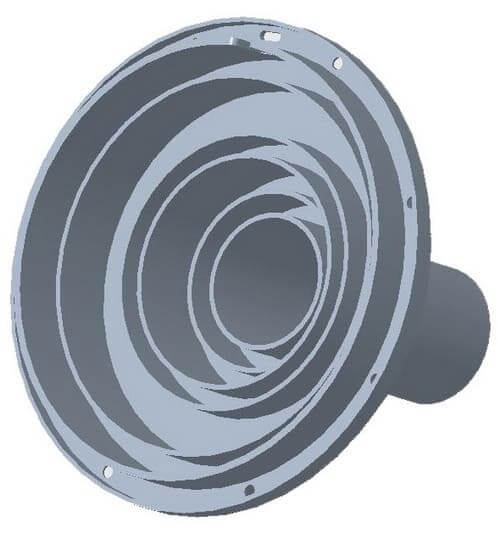
What is a Corrugated Horn Antenna?
As to the regular conical horn antenna, some currents flow from the inner wall to the outer space at the terminal opening due to discontinuity with the outer space at the terminal door. It affects the horn antenna’s performance a lot. A traditional λ/4 choke slot is added inside the horn to stop the current from flowing to the outer wall. That’s why the corrugated cone horn antenna has occurred.
Features:
- Broadband
- Definite phase center
- High beam efficiency
- Low sidelobe and backlobe
- Low cross-polarization level
- Rotational & symmetric radiation patterns
Applications:
- Antenna Measurement
- Fixed Wireless Networks
- Ultra-wideband Radar System
- Feedhorn /Feeder (parabolic reflector antenna)
What is Dual Polarization Horn Antenna?
A horn antenna with a rectangular waveguide boundary for both planar and vertical ports is called dual polarization horn antenna. It’s also named the dual linear polarization quad ridged horn antenna, which supports linear and elliptical polarized waveform.
The optional frequency ranges are included but not limited to 1-3GHz, 2-6GHz, 4.9-6.5GHz, 6-18GHz, 18-40GHz with an 8-20dBi gain and 50 ohms impedance. The interface can be N-type, SMA-type or 2.92mm series.
Features:
- Wide operating frequencies
- Compact and lightweight design
- Dual linear polarization
- Optional frequency ranges, gain, connectors
- Gold plated brass with High precision machining
Applications:
- Antenna Measurement
- Electromagnetic Measurement
- Electromagnetic Compatibility Testing
- Ultra-wideband Radar Detection
Alternative Methods for Converting Linear to Circular Polarization in Waveguides
Beyond the commonly used dielectric loading, several practical techniques exist to convert linear to circular polarization within waveguides:
- Squeezed Pipe Polarizers: This method involves slightly deforming (or “squeezing”) a section of the waveguide. The resulting asymmetry causes the orthogonal field components to experience different phase velocities, ultimately generating circular polarization at the output.
- Screw Polarizers: Metallized screws are inserted into the waveguide wall, typically at precise intervals and depths. By adjusting the depth and position of these screws, the phase shift between orthogonal modes can be finely controlled to achieve the desired circular (or elliptical) polarization.
- Wire-Grid or Plate Polarizers: Arrays of metallic wires or thin plates are placed at specific angles inside the waveguide. When properly oriented, these grids alter the relative phase and amplitude of the field components, enabling conversion to circular polarization—an approach often leveraged in satellite TV and amateur radio applications.
- Choke or Iris Structures: Additional irises or choke slots can be engineered within the waveguide to create the necessary phase delay and mode mixing, resulting in a circularly polarized output.
Each technique brings unique advantages depending on the frequency range, mechanical constraints, and required polarization purity. These solutions are popular in both commercial products and custom builds found throughout the RF/microwave and satellite industries.
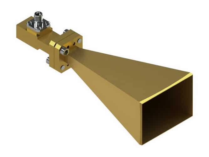
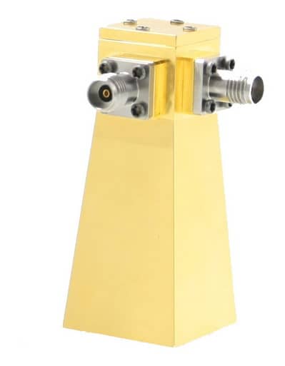
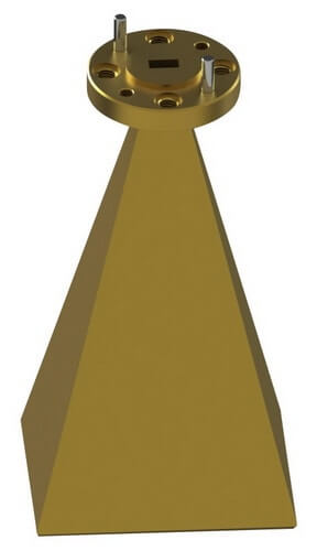
What is Millimeter Horn Antenna?
Millimeter horn antenna is the alternate name for Pyramidal Horn Antenna. The antenna body comes in the shape of a four-sided pyramid, guided by a rectangular cross-section with a rectangular waveguide interface. It’s also called Millimeter Standard Gain Horn Antenna.
The Pyramidal Horn Antenna operates from 26.5GHz to 325GHz with 50 ohms and linear polarization. It’s optional for the frequency range, gain and half-power beamwidth. The horn is made from copper with gold plated by high precision machining.
Features:
- Compact and lightweight design
- Linear Polarization
- Low VSWR, sidelobe and return loss
- Symmetrical radiation patterns
- Rectangular waveguide interface
- Gold plated brass with High precision machining
Applications:
- Antenna Measurement
- Electromagnetic Measurement
- High-Resolution Imaging
- Ultra-wideband Radar System
- Enhanced Ultra High Throughput (EUHT) Wireless Communication System
What is the Ridge Horn antenna ?
A Ridge horn antenna is an antenna with a ridge structure between the waveguide part and horn body. It’s also a broadband horn antenna. There are three major types of Ridge Horn Antennas: double ridge horn antenna, dual ridged horn antenna and quad ridge horn antenna. It’s dual linear polarization for the dual ridged horn antenna.
Ridge horn antenna operates from 0.1GHz to 40GHz with 50 ohms and 8-20dBi standard gain. The available interface includes 2.92mm and SMA-type connector.
Features:
- Wide band
- High gains, low VSWR
- Dual linear polarization
- High accuracy & high stability
- Optional frequency ranges, gain, interface
Applications:
- Antenna measurement
- Electromagnetic Compatibility Testing
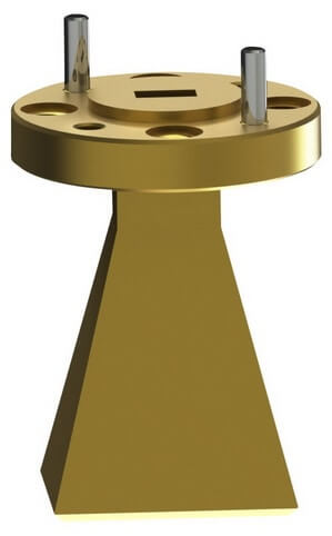
What is a Standard Gain Horn Antenna?
Standard gain horn antenna is the collective name of the horn antenna with symmetrical gain performance in a specific frequency range. It is a Pyramidal Horn Antenna. It includes both a rectilinear or curve edge horn body.
The operating frequency ranges from 0.96GHz to 12.4GHz for the rectilinear (regular)cross-section and 2.5-40GHz for the curve edge one. The gain varies from 10dBi to 25dBi at 0.96-12.4GHz for the regular standard gain horn antenna. It’s a fixed 15dBi during 2.5-40GHz for the curve edge standard gain horn antenna.
The standard gain horn antennas are made from brass and produced by high precision machining with very little tolerance. It can ensure precise, consistent and reliable performance.
How Are Standard Gain Horn Antennas Designed and Constructed?
The design and construction of standard gain horn antennas follow industry benchmarks developed over decades of research and precision engineering. Historically, meticulous calibration standards were established to ensure that these antennas delivered consistent, reliable gain across their specified frequency ranges.
Standard gain horn antennas are typically constructed using brass or copper, shaped precisely by high-accuracy machining to adhere to tightly controlled tolerances. These antennas are designed with specific dimensions that correspond directly to standard waveguide sizes, allowing for seamless integration with other RF and microwave components. The geometry—often pyramidal or incorporating curve edges for particular variants—ensures symmetrical radiation patterns and repeatable performance in laboratory and field settings.
Essentially, manufacturers follow rigorously documented construction parameters so that every standard gain horn antenna offers traceable, repeatable gain values for use as reference antennas in measurement, calibration, and testing applications. This tradition of precise specification and quality control is considered fundamental throughout laboratories and institutions worldwide, making standard gain horns a cornerstone of RF antenna measurement and system characterization.
Features:
- Wide frequency, low VSWR
- Symmetrical beam and gain
- Circular and Square Flanges
- Brass material with gold plated
- Optional frequency ranges, gain, interface
Applications:
- Antenna measurement
- Radar Detection System
- Wireless Communication
- Spectrum Monitoring
- Electromagnetic Interference
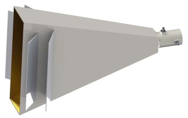
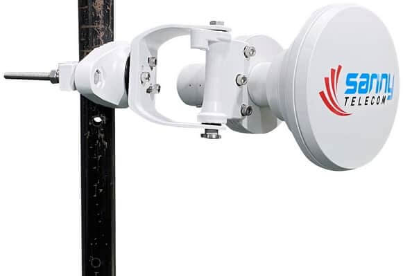
What is a Symmetrical Horn Antenna ?
Symmetrical Horn Antenna belongs to the Corrugated Horn Antenna. It has symmetrical radiation patterns in both vertical and horizontal planes with dual polarization. It’s a next-generation and game-changing sector antenna for point-to-multipoint communication.
Sanny Telecom Symmetrical Horn Antenna series operates from 5150MHz to 6500MHz with optional gain and half-power beamwidth. It also support WiFi 7 band 5925-7125MHz with an alternative feedhorn.
Features:
- Compact design
- Zero sidelobe
- Wideband, high gain
- High isolation& F/B ratio
- Symmetrical radiation patterns
- Outstanding beam performance
- N-female connectors
- All-weather operation
- Optional frequency range, gain, beamwidth
Applications:
- WiFi Hotspot
Horn Antenna FAQ
Do You Offer a Free Sample?
We always consider our customer’s needs to be the priority. Through our expert machinery and experienced professionals, we have continued to work in that direction for quite a few years now. When it comes to WiFi symmetrical horn antennas, we would be glad to offer a free sample. The free sample will help you understand the mechanism of the antenna chosen and how it will bring down your ordeals to a bare minimum.
Once we gain your confidence through our sample, our team of brainstorming professionals will put in their best ideas for any required alterations. Provided the model passes the test, we will work towards delivering you the final product and its guided installation as soon as possible.
Can You Customize a Horn Antenna to Suit Our Needs?
As we mentioned earlier, our customers are our utmost priority. Here, we invest our expertise to develop a product that meets the customer’s requirements. Provided you have any particular needs, feel free to communicate them to us. We would try our best to customize a horn antenna that falls in place with your desires and wishes.
How Do You Guarantee High Performance for Testing Purposes?
At RF Essentials, we house the best horn antenna experts from across the globe. Our team of expert professionals has experience of more than 15 years, ranking them above others. Throughout this journey of more than 15 years, they tried and tested to gain every bit of knowledge in this field. Their brainstorming ideas and practical solutions through horn antennas are testimonials to our high-performance results.
Over the years, the customers we have been serving are living testament to our expertise and reliability. Their know-how in the field of horn antennas would give nothing lesser than the perfect solution you are looking for!
You might feel that we are building castles in the air through our emphatic statements. Our detailed simulation test report will give a deep insight into the successful testing of the horn antennas, their specifications, and the ensuing result. Through our provision of such detailed information, we exhibit our skills in practical use.
How to Connect the Horn Antenna to Radios or Test Equipment?
Connecting the horn antenna won’t be much of a hassle. Here our experts will guide you through the procedure, thus preparing you for individual operations in the future. Under normal circumstances, we connect horn antennas through a high-performing pigtail, a coax cable assembly.
The cable assembly will allow the antenna to drive power from the source and begin its operations. Provided there are any discrepancies, the wire can get replaced. Thus, there is nothing to worry about as we will not leave any stone unturned before handing over a completed and efficient project to you.
What’s the Lead-Time of the Horn Antennas?
The lead time of horn antennas varies from one antenna type to another, with primary dependence on the order quantity. Every horn antenna type does not have a similar manufacturing procedure.
While some have a more straightforward procedure that consumes less time, some take more time to finish due to their complicated manufacturing. When we talk about the manufacturing procedure, it involves the technology and devices used in its making.
While some horn antenna types, like the standard gain horn antenna, are sufficiently available, some might not. Here the difference gets created regarding the lead time. It mainly depends on the horn antenna type and order quantity. Provided our inventories are sufficient, we will arrange for a quicker delivery.
The time consumption increases when the horn antenna requires customization. We use a high-precision CNC machine to ensure that the manufactured product gets customized to the highest quality.
Determining the Polarization of a Dielectric Plate Loaded Feed Horn
Understanding the polarization of a dielectric plate loaded feed horn doesn’t have to be complicated. The key lies in the purpose and orientation of the dielectric plate within the horn. Typically, these plates are set at a 45º angle to the two main axes inside the horn antenna. Their job is to introduce a specific phase shift—usually 90º—between orthogonal components of the TE11 mode.
Here’s how it works:
- The dielectric plate, commonly made from low-loss materials like PTFE, delays one component of the incoming wave relative to the other.
- This phase shift causes the two linear components of the TE11 mode to combine into a circularly polarized wave as the signal passes through the plate.
To figure out the direction—whether it’s right-hand circular polarization (RHCP) or left-hand (LHCP)—observe the plate’s orientation. If a linearly polarized wave enters the feed horn and meets the dielectric plate at 45º, the resultant rotation (right or left) depends on which side the signal originates from and the plate’s specific alignment.
A practical tip:
- If the TE11 mode enters the horn from the back and strikes the dielectric plate at 45º, the result is typically a right-hand circularly polarized output.
- Reversing the signal or the plate’s angle reverses the polarization direction.
Always double-check the plate’s material to ensure it suits your operating frequency with minimal insertion loss. This simple assessment will give you a clear idea of your horn’s polarization and help you select the appropriate configuration for your application.
Where Can I Find More Information on Waveguide Polarizers?
Looking to dig deeper into the world of waveguide polarizers? We understand this can be quite a specialized topic, and information sometimes hides in obscure corners. While comprehensive resources may be limited, you can often find technical discussions, ideas, and practical solutions in niche communities such as satellite TV forums, radio enthusiast websites, and academic patent databases.
Here are some helpful avenues to explore:
- Amateur Radio Communities: Many dedicated radio enthusiasts share their experiences and technical notes on polarizers, often including practical modifications or experimentation. For instance, visiting sites like EME (Earth-Moon-Earth) conference archives or forums hosted by amateur radio operators can often reveal detailed user guides and design notes.
- Patent Libraries: A search through online patent databases often uncovers innovative designs and documentation around polarizer devices, their functioning, and variations like screw polarizers or waveguide twists.
- Technical Forums and Tutorials: Satellite TV hobbyist sites sometimes offer real-world usage tips and descriptions, even if details are sometimes minimal. Don’t overlook international forums—sometimes the most practical insights come from seasoned users sharing field-tested setups.
For especially technical or tailored solutions, engaging with the broader engineering or enthusiast communities can help spark new ideas or provide alternate approaches. If you’re looking for specific advice or documentation, don’t hesitate to reach out—we’re always glad to help point you toward the right resources.