 Skip to content

Slotted waveguide antennas are crucial for enhancing WiFi communication systems. These antennas significantly improve signal strength, coverage, and reliability, making them indispensable for high-performance wireless networks. With their efficient design and ability to support both horizontal and vertical polarizations, slotted waveguide antennas are a key component in modern WiFi technology.
A slotted waveguide antenna is a specialized antenna used in WiFi communication systems to enhance signal strength and coverage. It features slots in a waveguide that emit radio waves, allowing for efficient signal transmission. This type of antenna supports dual polarization, meaning it can handle both horizontal and vertical polarizations simultaneously, improving the reliability and performance of WiFi networks.
Now, let’s delve deeper into the various aspects of slotted waveguide antennas to understand their functionality and benefits.
What is a slot antenna?
A slot antenna is a type of antenna used in wireless communications, characterized by a slot or a narrow rectangular cut in a metal surface. This design allows it to efficiently transmit and receive radio frequency signals. Slot antennas are known for their compact size, ease of integration into various devices, and ability to provide consistent performance across a wide range of frequencies. They are commonly employed in applications such as Wi-Fi, cellular networks, and other wireless communication systems.
What is the slotted waveguide antenna used for?
The slotted waveguide antenna is used in WiFi and MIMO (multiple-input, multiple-output) systems. These antennas provide high gain and low interference, making them ideal for communication applications. They are particularly useful in systems that require precise directional control and high efficiency.

How does the Slotted Waveguide Antenna work?
The Slotted Waveguide Antenna works by guiding radio waves through a waveguide and radiating them through slots, creating a directional beam. The waveguide is a hollow metallic tube that acts as a transmission line for the radio waves. The slots in the waveguide allow the radio waves to escape and radiate into free space.
The position and size of the slots are critical to the antenna’s performance. The slots act as radiating elements, and their position determines the direction in which the antenna radiates. By changing the position and size of the slots, the antenna can be designed to radiate in a specific direction or have a specific radiation pattern.

The size of the slots also affects the efficiency of the antenna. If the slots are too small, the radio waves will not be able to radiate effectively, resulting in poor performance. If the slots are too large, the antenna will be less efficient and may not radiate in the desired direction.
Beamwidth Characteristics
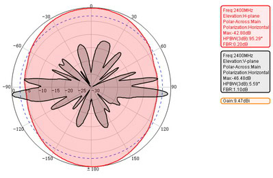
It’s also important to note that the slotted waveguide antenna exhibits different beamwidths in different planes. In the x-z plane (also known as the H-plane), the beamwidth is very narrow—typically between 2 to 5 degrees—making it highly directional. In contrast, the y-z plane (or E-plane) features a much wider beamwidth. This unique characteristic allows for concentrated transmission in one direction while providing broader coverage in the perpendicular plane. For applications that demand a pencil-type beam, further adjustments to the slot arrangement and waveguide design can be made to achieve an even tighter directional focus.
Overall, the Slotted Waveguide Antenna is a simple and efficient design that is commonly used for applications such as radar systems, satellite communications, and wireless networking. Its directional beam and high gain make it ideal for long-range communication.
Why is the last slot positioned a quarter-wavelength from the end?
In slotted waveguide antenna design, the placement of the last slot relative to the shorted end of the waveguide is crucial for optimal performance. Typically, this slot is set a quarter-wavelength away from the end. This isn’t just a design tradition—it’s rooted in transmission line theory.
When you short-circuit the end of the waveguide and place the last slot exactly a quarter-wavelength away, the short is effectively transformed into an open circuit at the position of the slot. In practical terms, this means maximum radiated energy can be extracted from the slot, since the transformed impedance is ideal for efficient radiation. This clever arrangement reduces reflections and maximizes the antenna’s overall efficiency.
By following this quarter-wavelength rule, engineers ensure that the energy traveling down the waveguide is transferred effectively to free space with minimal losses—a simple trick that has stood the test of time in both radar and communication antenna designs.
What is the working principle of a slotted antenna?
The working principle of a slotted antenna is based on the concept of aperture coupling. In this antenna, slots are cut into the conducting surface of a waveguide. When a microwave signal is applied to the waveguide, it propagates through the waveguide and reaches the slots. As the signal passes through the slots, it radiates out into space.
The slots act as apertures, allowing the microwave signal to escape from the waveguide and radiate as electromagnetic waves. The size and shape of the slots determine the frequency at which the antenna operates.
The slotted antenna can radiate energy in a specific direction, depending on the size and shape of the slots. By changing the dimensions of the slots, the radiation pattern of the antenna can be controlled.
The slotted antenna is a popular choice for applications where a narrow beam of radiation is required, such as in radar systems. It is also used in satellite communication systems, where the antenna needs to be able to track a moving satellite.
What are the advantages of a slotted antenna?
Some advantages of a slotted antenna are:
1. High Efficiency: Slotted antennas have high radiation efficiency, meaning that a large portion of the input power is converted into radiated power. This makes them suitable for applications where maximum power transfer is desired.
2. Low Cross-Polarization: Slotted antennas exhibit low cross-polarization, which means that they radiate and receive signals primarily in one polarization (either horizontal or vertical). This is important in applications where cross-polarization can cause signal degradation.
3. Flexibility in Design: Slotted antennas can be designed to operate over a wide range of frequencies, making them versatile for different applications. They can also be designed to have different radiation patterns, such as omnidirectional or directional, depending on the specific requirements.
4. High Power Handling Capability: Slotted antennas are capable of handling high power levels without significant degradation in performance. This makes them suitable for applications that require high power transmission, such as radar systems.
5. Covert Applications: Slotted antennas can be designed to be low-profile and inconspicuous, making them suitable for covert applications where it is desirable to hide the presence of an antenna.
6. Easy Mass Production and Customization: Slotted antennas can be easily mass-produced using standard manufacturing techniques, such as printed circuit board (PCB) fabrication. They can also be easily customized to meet specific requirements in terms of size, shape, and frequency response.
What is the disadvantage of slot antennas?
Disadvantages can include complexity in design and manufacturing, and potential limitations in bandwidth compared to other antenna types. Ensuring the precise placement and size of slots can be challenging.
Another disadvantage of slot antennas is that they are highly directional. This means that they have a narrow beamwidth and are only effective in transmitting or receiving signals in a specific direction. This can limit their usefulness in certain applications where a more omnidirectional coverage is required.
Slotted Waveguide Antenna Radiation Patterns
The arrangement of slots in these antennas allows for customization of the radiation pattern, enabling the creation of directional beams with different sizes and shapes. This adaptability makes them suitable for various environments and applications.
For example, a simple rectangular slot can produce a broadside radiation pattern, which is ideal for applications that require a wide coverage area. On the other hand, a narrower slot can produce a more focused radiation pattern, suitable for long-range communication or point-to-point links.
The shape of the slot can also affect the radiation pattern. For instance, a circular slot can produce a circularly polarized radiation pattern, which is useful for satellite communication and radar systems. Similarly, a slot with multiple arms can create a radiation pattern with multiple lobes, enabling the antenna to cover multiple directions simultaneously.
In addition to the slot arrangement, the size of the slot can also impact the radiation pattern. A larger slot will produce a wider beam, covering a larger area. Conversely, a smaller slot will create a narrower beam, providing more focused coverage.
In summary, slotted waveguide antennas offer flexibility in shaping the radiation pattern to meet specific requirements. By adjusting the slot arrangement, shape, and size, these antennas can provide directional beams with varying shapes and sizes, making them suitable for a wide range of applications.
Beamwidth Differences in the H-Plane and E-Plane
When it comes to slotted waveguide antennas, the beamwidth varies significantly depending on the plane in which the radiation is measured.
- In the x-z plane (also known as the H-plane), the beam produced by a slotted waveguide antenna is quite narrow—typically ranging from only 2 to 5 degrees. This characteristic makes these antennas an excellent choice for applications that require highly focused, long-distance communication, such as radar or point-to-point wireless links.
- In contrast, the y-z plane (or E-plane) exhibits a much broader beamwidth. This means the antenna covers a wider area in this direction, making it possible to reach more devices or provide greater area coverage within that plane.
This sharp difference between the narrow H-plane and the wider E-plane beamwidth is a defining feature of slotted waveguide antennas, and it can be leveraged to suit the directional or coverage requirements of various wireless systems.
Why are slot elements typically spaced about a half-wavelength apart?
Slot elements in a slotted waveguide antenna are generally spaced at approximately half the wavelength of the operating frequency. This particular spacing isn’t arbitrary—it’s chosen to ensure that the impedance looking into each slot remains consistent throughout the antenna, making the design much simpler.
When you space the slots by half a wavelength, the currents in each slot are in phase, leading to constructive interference in the desired direction. This ensures that each slot contributes efficiently to the overall radiation pattern without introducing unwanted phase shifts or impedance mismatches.
In practical terms, this spacing allows all the slots to function as if they’re connected in parallel, simplifying the impedance matching. The result is an antenna that radiates effectively and predictably, with each slot reinforcing the others, much like synchronized swimmers moving as a team rather than bumping into each other in the pool.
This approach is widely adopted because it offers a good balance between efficient radiation and ease of design, supporting both performance and manufacturability.
Slotted Waveguide Antenna Frequency
Slotted waveguide antennas can be used for WiFi applications in both single-band and dual-band configurations, including those with multiple-input multiple-output (MIMO) technology.
For single-band WiFi, the slotted waveguide antenna can be designed to operate at the desired frequency, such as 2.4 GHz or 5 GHz. These antennas are typically used for applications that require a specific frequency band, such as 2.4 GHz for 802.11b/g/n or 5 GHz for 802.11a/n/ac.
In the case of dual-band WiFi, the slotted waveguide antenna can be designed to operate at both 2.4 GHz and 5 GHz. These antennas are commonly used in dual-band routers or access points that support both 2.4 GHz and 5 GHz WiFi networks. They allow devices to connect to either frequency band based on their capabilities and requirements.
When it comes to MIMO technology, slotted waveguide antennas can be designed with multiple slots to support multiple antennas. For example, a dual-band WiFi router with MIMO could have two slotted waveguide antennas, each with multiple slots, to support multiple streams of data transmission and reception. This enables higher data rates and improved wireless performance.
Overall, slotted waveguide antennas can be designed and used for WiFi applications in single-band, dual-band, and MIMO configurations, providing efficient and reliable wireless connectivity.
Slotted Waveguide Antenna Polarization
Dual polarization in the context of slotted waveguide antennas refers to the ability of the antenna to radiate and receive signals with both horizontal and vertical polarizations simultaneously. This means that the antenna is capable of transmitting and receiving signals in two different planes.
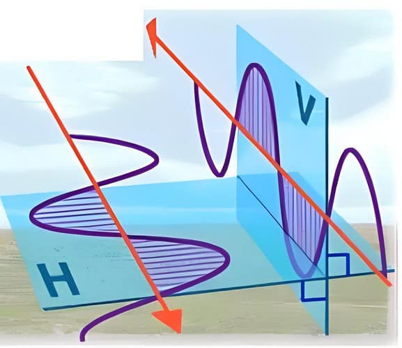
In a dual-polarized slotted waveguide antenna, the slots are oriented in such a way that they can radiate and receive signals in both the horizontal and vertical planes. This is achieved by having two sets of slots, one for each polarization. The slots for horizontal polarization are aligned in the vertical plane, while the slots for vertical polarization are aligned in the horizontal plane.
By having dual polarization, the antenna can transmit and receive signals in two different polarizations simultaneously. This is particularly useful in scenarios where the signal environment is complex and consists of signals with different polarizations. By being able to receive signals with both horizontal and vertical polarizations, the antenna can effectively capture more of the available signal power and enhance the overall performance.
Dual polarization can also be beneficial in applications where there is a need to transmit and receive signals with different polarizations simultaneously. For example, in wireless communication systems, different users may be assigned different polarizations to minimize interference between them. In such cases, a dual-polarized antenna can be used to transmit and receive signals with different polarizations simultaneously, allowing for efficient communication.
Overall, dual polarization in slotted waveguide antennas allows for enhanced performance in complex signal environments and enables the antenna to transmit and receive signals with different polarizations simultaneously.
Operating Below the Cutoff Frequency
When the frequency falls below the cutoff frequency of a waveguide, the antenna essentially stops functioning as intended. At these lower frequencies, electromagnetic waves are unable to propagate through the waveguide; instead, they become attenuated rapidly and decay before ever reaching the slots or being radiated.
As a result, little to no energy escapes into free space, and the antenna loses its ability to transmit or receive signals efficiently. This behavior is crucial to keep in mind when designing slotted waveguide antennas to ensure reliable operation within the desired frequency range.
Bandwidth and Resonance Characteristics Near 10 GHz
When operating around 10 GHz, a slotted waveguide antenna typically exhibits a sharp response centered on its design frequency. The antenna radiates most efficiently at this frequency, resulting in a significant drop in reflected power (S11) close to 10 GHz.
The usable bandwidth—often defined as the frequency range where S11 remains below -6 dB—usually spans roughly 800 MHz, or about 8% fractional bandwidth. In practical terms, this means the antenna effectively covers from approximately 9.7 GHz to 10.5 GHz. Within this range, most of the signal energy is radiated and the antenna performs optimally.
It’s also common to observe additional resonances within the operating frequency range. For example, smaller resonant dips may appear around 6.7 GHz and 9.2 GHz. Note, however, that frequencies below about 6.5 GHz fall below the waveguide’s cutoff, so energy is not efficiently radiated there.
In summary, a slotted waveguide antenna designed for 10 GHz delivers a concise operational bandwidth centered on its target frequency, with steep roll-off outside this band and characteristic resonances at lower frequencies.
Understanding S-Parameter (S11) Measurements for Slotted Waveguide Antennas
When it comes to analyzing the frequency response and bandwidth of a slotted waveguide antenna, S-parameter measurements—specifically S11—are incredibly useful. The S11 parameter, commonly referred to as the reflection coefficient, indicates how much power is reflected back from the antenna instead of being radiated.
A deep dip in the S11 value (typically well below -6 dB) at a particular frequency suggests that the antenna is efficiently radiating power at that frequency. For example, if you see a significant drop in S11 around 10 GHz, this means the antenna is well-matched and most of the signal is being transmitted rather than reflected.
The bandwidth of the antenna can be determined by identifying the range of frequencies over which the S11 stays below a certain threshold, like -6 dB. If S11 is lower than -6 dB from approximately 9.7 GHz to 10.5 GHz, the antenna’s effective bandwidth is that 0.8 GHz span—about 8% fractional bandwidth relative to the center frequency. Additional resonant dips in S11 at other frequencies, such as 6.7 GHz or 9.2 GHz, may indicate the presence of other modes or harmonics, but efficient radiation occurs primarily in the main bandwidth region.
It’s also important to note that below a specific frequency, often the waveguide cutoff (for example, below 6.5 GHz), the S11 value rises sharply, indicating that the waveguide is no longer supporting propagation, and almost all energy is reflected.
By reviewing the S11 graph, engineers can quickly assess where the antenna is most efficient, how wide the usable bandwidth is, and spot key resonances that affect performance.
Slotted Waveguide Antenna Theory
A slotted waveguide antenna is a type of antenna that operates by guiding electromagnetic waves along a metallic waveguide and then radiating them through slots cut into the waveguide walls. This design allows for efficient transmission and reception of electromagnetic waves, especially at high frequencies.
The basic principle behind a slotted waveguide antenna is the propagation of electromagnetic waves through a waveguide. A waveguide is a metallic structure that is designed to guide electromagnetic waves along its length with minimal signal loss. The waveguide is typically rectangular or circular in shape and is made of a conductive material such as metal.
When an electromagnetic wave enters a waveguide, it is confined within the waveguide by the reflective walls. The wave propagates along the length of the waveguide, bouncing off the walls until it reaches the desired destination.
In a slotted waveguide antenna, slots are cut into the walls of the waveguide at specific locations. These slots act as radiating elements, allowing the electromagnetic waves to escape the waveguide and radiate into free space. The size, shape, and placement of the slots determine the radiation pattern and the characteristics of the antenna.
The slots in a slotted waveguide antenna are typically small compared to the wavelength of the electromagnetic wave. This ensures that the slots do not significantly affect the propagation of the wave along the waveguide. Instead, the slots act as small apertures that allow the wave to radiate into free space.
The slots in a slotted waveguide antenna can be arranged in various configurations to achieve different radiation patterns. For example, a single row of slots along one side of the waveguide will produce a broadside radiation pattern, while multiple rows of slots on opposite sides of the waveguide will produce an endfire radiation pattern.
Slotted waveguide antennas are commonly used in high-frequency applications, such as radar systems and satellite communications. They offer high directivity, which means they can focus the radiated energy in a specific direction, allowing for long-range communication. Additionally, the metallic waveguide provides shielding, protecting the antenna from interference and improving its performance.
In summary, a slotted waveguide antenna operates by guiding electromagnetic waves along a metallic waveguide and then radiating them through slots cut into the waveguide walls. This design allows for efficient transmission and reception of electromagnetic waves, especially at high frequencies. Slotted waveguide antennas are widely used in high-frequency applications due to their high directivity and low signal loss.
Role of Guide Wavelength in Slotted Waveguide Antenna Design
The concept of guide wavelength is fundamental to determining how and where to place slots along the waveguide. Unlike the wavelength in free space, the guide wavelength takes into account the physical dimensions of the waveguide—mainly its width—and the manner in which electromagnetic waves propagate within it. For common rectangular waveguides operating in the dominant TE10 mode, this guide wavelength is typically longer than the free-space wavelength.
When it comes to arranging the slots, both their spacing and their distance from the waveguide’s end depend heavily on this guide wavelength:
- Slot Spacing (L): Usually, slots are spaced about half a guide wavelength apart. This spacing ensures constructive interference and optimal radiation in the desired direction. By keeping this interval at approximately half a guide wavelength, the antenna maintains consistent impedance characteristics, allowing the slots to effectively act as elements in parallel.
- Distance from the End (d): The final slot is commonly positioned about a quarter of the guide wavelength from the closed (short-circuited) end of the waveguide. This quarter-wavelength placement leverages transmission line theory, effectively presenting an open circuit at the end slot due to the impedance transformation caused by the quarter-wavelength section. This approach maximizes energy transfer and minimizes reflections.
In summary, guide wavelength directly informs the physical layout of slots in a slotted waveguide antenna. Careful calculation of slot spacing and their offset from the end ensures that the antenna radiates efficiently and achieves the desired impedance characteristics—all crucial for high-performance applications such as radar and satellite communications.
Slot Spacing and Its Importance
The arrangement of slots along the waveguide plays a crucial role in how effectively a slotted waveguide antenna radiates energy and matches impedance. Two spacing distances deserve special mention: the gap between each slot and the distance from the final slot to the end of the waveguide.
Spacing Between Slots
Slots are usually spaced about half a wavelength apart along the waveguide. This particular distance is no coincidence—spacing the slots by half a wavelength ensures that the energy radiated from each slot adds together in-phase, reinforcing the desired signal and creating a well-defined, directional radiation pattern. With this configuration, the slots effectively behave as parallel radiators, each contributing constructively to the antenna’s overall performance.
Distance from the Last Slot to the Waveguide End
The distance from the last slot to the end of the waveguide, often set to a quarter-wavelength, is another intentional design choice. The reason for this goes back to transmission line theory: when the end of the waveguide is short-circuited, positioning the last slot a quarter-wavelength away transforms the short circuit into an open circuit at the slot’s location. This clever trick helps minimize energy reflection back into the waveguide, efficiently directing power out through the slots instead.
By carefully choosing both the inter-slot spacing and the termination spacing, designers ensure not only an optimal radiation pattern but also proper impedance matching—key factors for maximizing efficiency and performance in real-world applications, from radar arrays to satellite ground terminals.
Calculating Input Admittance and Impedance in Multi-Slot Arrays
When designing a multi-slot slotted waveguide antenna, it’s crucial to understand how the arrangement of slots affects the overall input admittance and impedance of the array. Let’s explore how these key parameters are determined.
Slot Spacing and Electrical Length
The spacing between adjacent slots (L) is typically set at around half the guide-wavelength (λg) within the waveguide. This guide-wavelength depends on the waveguide’s width (denoted a) and the operating frequency, and is generally longer than the wavelength in free space due to the waveguide’s cutoff characteristics.
Short-Circuited End and Quarter-Wave Transformation
Usually, the last slot is positioned a quarter guide-wavelength from the short-circuited end of the waveguide. According to transmission line principles, a short circuit placed a quarter-wavelength from the slots transforms into an open circuit at the slot positions, preventing unwanted reflection and improving impedance matching.
Parallel Slot Admittance in Arrays
With each slot spaced at approximately half a guide-wavelength, the impedance seen when looking back through the array remains consistent at each segment—essentially, the impedance repeats every half-wavelength. Because of this, all slots act in parallel electrically. This makes calculating the total input admittance straightforward: simply add up the individual slot admittances.
Total Input Admittance = N × (Admittance of one slot),where N is the number of slots.
Total Input Impedance is the reciprocal of the total admittance: 1 / (N × [Admittance of one slot]).
The specific admittance and impedance of each slot can be tuned by adjusting the slot’s length, width, orientation, and position along the waveguide, allowing precise control over the antenna’s performance.
By configuring both the slot locations and the shorted end thoughtfully, you ensure the slots combine synergistically, making it possible to design efficient slotted waveguide arrays for applications ranging from aerospace radar to satellite communications.
Circuit Model of a Slotted Waveguide Antenna
To better understand the operation of a slotted waveguide antenna, it helps to visualize its equivalent circuit. In simple terms, the waveguide acts as a transmission line, while each slot behaves like a shunt (parallel) admittance connected along the line. The typical design has the end of the waveguide short-circuited, which is essential for the antenna’s operation.
Imagine each slot as a small “leak” point for electromagnetic energy—these correspond to circuit elements that let current flow out of the transmission line. The slots are usually spaced a distance L apart, and the last slot sits a distance d from the short-circuited end.
When building the circuit model, it’s common to express these distances as fractions of the guide wavelength (the wavelength of the signal inside the waveguide rather than in free space). For instance:
- The gap between the final slot and the end (d) is often set to a quarter of the guide wavelength. This specific value transforms the short at the end into an effective open circuit at the location of the slot, thanks to basic transmission line theory.
- The distance between individual slots (L) typically equals about half the guide wavelength. This spacing ensures that each slot “sees” the same impedance, which simplifies analysis and design.
With these arrangements, all slots appear in parallel from an electrical point of view. This layout makes calculating the total input admittance (and therefore the input impedance) straightforward: simply sum the admittances of all slots. The input impedance of the entire antenna depends on both the number of slots and on their individual impedance characteristics.
Slotted Waveguide Antenna Design
There are several steps involved in designing a slotted waveguide antenna:
1. Determine the operating frequency: The first step is to determine the frequency at which the antenna will operate. This will dictate the dimensions of the waveguide and the slot.
2. Choose the waveguide dimensions: The dimensions of the waveguide, such as width and height, need to be chosen based on the desired operating frequency. This can be done using standard waveguide design equations or software tools.
3. Determine the slot dimensions: The dimensions of the slot, such as length and width, need to be chosen based on the desired operating frequency and the desired radiation pattern. The slot should be small enough to radiate at the desired frequency but large enough to achieve the desired radiation pattern.
It’s important to note that these design parameters are optimized for a specific frequency. As the antenna operates at frequencies farther from the design frequency, its performance will degrade. For example, if a waveguide is designed to operate at 10 GHz, it will exhibit optimal characteristics—such as strong radiation and low signal reflection—near that frequency. This is often illustrated by measuring the S11 parameter (a measure of how much power is reflected back into the feed rather than radiated), which drops significantly near the design frequency, indicating efficient radiation.
The bandwidth of a slotted waveguide antenna is typically defined as the frequency range where S11 remains below -6 dB. For a waveguide designed at 10 GHz, the bandwidth might extend from around 9.7 GHz to 10.5 GHz, resulting in a fractional bandwidth of about 8%. It’s also common to observe resonances at other frequencies, but below a certain cutoff frequency (for example, 6.5 GHz for some designs), the waveguide will not radiate effectively.
By keeping these frequency characteristics in mind during the design process, you can ensure that your slotted waveguide antenna performs efficiently within the intended frequency range and meets the requirements of your application.
4. Determine the slot position and orientation: The position and orientation of the slot within the waveguide need to be chosen to achieve the desired radiation pattern. This can be done using modeling and simulation tools or by trial and error.
5. Calculate the feed position: The position of the feed within the waveguide needs to be determined to achieve the desired radiation pattern. This can be done using modeling and simulation tools or by trial and error.
Typically, the antenna is fed at the front end—often the open face of the waveguide (at y = 0 in the x-z plane). The far end of the waveguide is usually shorted by enclosing it in metal. Excitation can be achieved in several ways, such as using a short dipole inside the waveguide or by coupling in energy from another waveguide. Careful selection of the feed method and location is crucial, as it directly influences the antenna’s efficiency and its resulting radiation characteristics.
6. Model and simulate the design: Once the slot position, orientation, and feed position have been determined, the design can be modeled and simulated using electromagnetic simulation software. This will allow the designer to verify that the design meets the desired specifications.
7. Fabricate and test the antenna: After the design has been verified through simulation, the antenna can be fabricated and tested. This will involve machining the waveguide and slot, as well as fabricating the feed. The antenna can then be tested to ensure that it meets the desired specifications.
8. Optimize the design: If the antenna does not meet the desired specifications, the design can be optimized by adjusting the slot dimensions, position, orientation, or feed position. This can be done through a combination of modeling, simulation, and testing.
Phased Array Slotted Antenna vs. Slotted Waveguide Antenna
Phased array slotted antenna:
– Consists of a large number of individual radiating elements, each with its own phase shifter.
– The elements are arranged in a regular pattern, such as a grid or a circle.
– By adjusting the phase of each element, the antenna can steer the beam in different directions.
– Offers high flexibility in beam steering and can track multiple targets simultaneously.
– Can be used for applications such as radar, satellite communication, and wireless communication.
– More complex and expensive to design and build compared to slotted waveguide antennas.
Slotted waveguide antenna:
– Consists of a waveguide with a narrow slot cut into it.
– The slot radiates electromagnetic waves, and the shape and size of the slot determine the antenna’s radiation pattern.
– The antenna is designed to radiate most of its energy in a specific direction.
– Typically exhibits a highly directional radiation pattern, with a narrow beamwidth in one plane (often 2–5 degrees in the x-z or h-plane) and a much wider beamwidth in the perpendicular plane (the y-z or e-plane). This creates a distinct, focused “pencil” beam ideal for applications like point-to-point links or radar.
– The 3D radiation pattern of a typical slotted waveguide antenna demonstrates significant gain—often around 17 dB—which is advantageous for long-distance communication and high-frequency applications.
– Achieving specific beam shapes, such as a narrower pencil beam, is possible by further optimizing slot placement and orientation, a topic often explored in advanced antenna design.
– Typically used for applications that require a fixed beam direction, such as point-to-point communication links or radar systems.
– Requires fewer elements compared to phased array antennas.
– Simpler and less expensive to design and build compared to phased array antennas.
Summary
Slotted waveguide antennas are important for improving WiFi and MIMO (Multiple Input Multiple Output) systems, which are critical for wireless communication today. These antennas are great at handling high frequencies and supporting different polarizations, which makes them perfect for increasing the strength and range of WiFi networks.
Moreover, their design makes it easy to use MIMO technology, which uses multiple antennas to send and receive signals, improving the speed and reliability of data. Knowing how slotted waveguide antennas work can help you make wireless communication systems work better and stay connected.