 Skip to content

In today’s technologically driven world, understanding the basics of the devices we use daily is crucial. Among these, antenna elements play a pivotal role in communication systems. But what exactly is an antenna element, and why is it important?
An antenna element is the fundamental building block of an antenna array, designed to transmit or receive electromagnetic waves. These elements can range from simple dipoles to complex shapes, depending on their specific application in broadcasting, receiving signals, or radar systems.
Now that we’ve touched on what an antenna element is, let’s delve deeper into how they work and their significance in modern technology.
How does the antenna element work?
The antenna element consists of a conductive material, such as metal, that is designed to efficiently radiate or receive electromagnetic waves at a specific frequency or range of frequencies. The size and shape of the antenna element are carefully designed to match the desired frequency of operation.
When an electrical signal is applied to the antenna element, it causes the electrons in the conductive material to move back and forth, creating an oscillating current. This oscillating current generates an oscillating electric field around the antenna element.
According to Maxwell’s equations, a changing electric field creates a magnetic field, and a changing magnetic field creates an electric field. As the electric field and the magnetic field continuously change and interact with each other, they propagate away from the antenna as an electromagnetic wave.
The radiation pattern of the antenna element determines the directionality of the electromagnetic waves it radiates or receives. The shape and orientation of the antenna element determine the shape and direction of the radiation pattern. For example, a dipole antenna element, which consists of two conductive elements aligned in opposite directions, radiates or receives electromagnetic waves most efficiently in a donut-shaped pattern perpendicular to the antenna.
Understanding Radiation Patterns
A radiation pattern—also known as an antenna pattern—is a graphical or mathematical representation of how an antenna radiates energy into space. Typically defined for the far-field region, this pattern shows the variation of radiated power as a function of direction, often using spherical coordinates. Here, the azimuth ((\phi)) represents the angle around the horizon, while the elevation ((\theta)) indicates how high above the horizon the measurement is taken.
Radiation patterns can be expressed in terms of either the magnitude of the electric or magnetic field (field patterns) or the power (power patterns), the latter often shown in decibels (dB) and normalized to the pattern’s maximum value.
Key Features of Radiation Patterns
- Main Lobe: The region of strongest radiation—this is usually where the antenna is “aimed.”
- Minor Lobes: These are smaller regions of radiation away from the main lobe, which include:
- Side Lobes: Typically the largest of the minor lobes, extending out at angles to the main lobe.
- Back Lobe: Radiation in the direction opposite to the main lobe.
- cURL Too many subrequests by single Worker invocation. To configure this limit, refer to https://developers.cloudflare.com/workers/wrangler/configuration/#limits cURL Too many subrequests by single Worker invocation. To configure this limit, refer to https://developers.cloudflare.com/workers/wrangler/configuration/#limits.
- cURL Too many subrequests by single Worker invocation. To configure this limit, refer to https://developers.cloudflare.com/workers/wrangler/configuration/#limits cURL Too many subrequests by single Worker invocation. To configure this limit, refer to https://developers.cloudflare.com/workers/wrangler/configuration/#limits.
cURL Too many subrequests by single Worker invocation. To configure this limit, refer to https://developers.cloudflare.com/workers/wrangler/configuration/#limits
cURL Too many subrequests by single Worker invocation. To configure this limit, refer to https://developers.cloudflare.com/workers/wrangler/configuration/#limits.
cURL Too many subrequests by single Worker invocation. To configure this limit, refer to https://developers.cloudflare.com/workers/wrangler/configuration/#limits.
cURL Too many subrequests by single Worker invocation. To configure this limit, refer to https://developers.cloudflare.com/workers/wrangler/configuration/#limits
cURL Too many subrequests by single Worker invocation. To configure this limit, refer to https://developers.cloudflare.com/workers/wrangler/configuration/#limits cURL Too many subrequests by single Worker invocation. To configure this limit, refer to https://developers.cloudflare.com/workers/wrangler/configuration/#limits, cURL Too many subrequests by single Worker invocation. To configure this limit, refer to https://developers.cloudflare.com/workers/wrangler/configuration/#limits, cURL Too many subrequests by single Worker invocation. To configure this limit, refer to https://developers.cloudflare.com/workers/wrangler/configuration/#limits, cURL Too many subrequests by single Worker invocation. To configure this limit, refer to https://developers.cloudflare.com/workers/wrangler/configuration/#limits cURL Too many subrequests by single Worker invocation. To configure this limit, refer to https://developers.cloudflare.com/workers/wrangler/configuration/#limits. cURL Too many subrequests by single Worker invocation. To configure this limit, refer to https://developers.cloudflare.com/workers/wrangler/configuration/#limits.
cURL Too many subrequests by single Worker invocation. To configure this limit, refer to https://developers.cloudflare.com/workers/wrangler/configuration/#limits
- Main Lobe: cURL Too many subrequests by single Worker invocation. To configure this limit, refer to https://developers.cloudflare.com/workers/wrangler/configuration/#limits.
- Minor Lobes: cURL Too many subrequests by single Worker invocation. To configure this limit, refer to https://developers.cloudflare.com/workers/wrangler/configuration/#limits.
- Side Lobes: cURL Too many subrequests by single Worker invocation. To configure this limit, refer to https://developers.cloudflare.com/workers/wrangler/configuration/#limits.
cURL Too many subrequests by single Worker invocation. To configure this limit, refer to https://developers.cloudflare.com/workers/wrangler/configuration/#limits cURL Too many subrequests by single Worker invocation. To configure this limit, refer to https://developers.cloudflare.com/workers/wrangler/configuration/#limitscURL Too many subrequests by single Worker invocation. To configure this limit, refer to https://developers.cloudflare.com/workers/wrangler/configuration/#limits.
Understanding Beamwidth
- Beamwidth measures how narrowly or widely your antenna radiates energy around its main lobe. Formally, it’s the angular spread between the points on either side of the main lobe where the signal drops to half its maximum strength (often called the half-power points).
- A narrower beamwidth means a more focused signal—great for pinpoint communication (think satellite dishes). However, narrowing the beam often increases the size of side lobes, so there’s a trade-off to balance depending on the application.
To put it all together, imagining an ideal, theoretical “isotropic radiator”—an antenna that spreads energy equally in all directions—can help clarify. Real-world antennas shape their energy in specific patterns, giving rise to main lobes, side lobes, and a definable beamwidth, all of which influence the antenna’s performance in any wireless application.
When an electromagnetic wave from another antenna or transmitter encounters the antenna element, the changing electric and magnetic fields of the wave induce a current in the antenna element. This current is then used to extract the information or signal carried by the electromagnetic wave.
In summary, the antenna element converts electrical signals into electromagnetic waves for transmission and converts received electromagnetic waves into electrical signals for reception. It does this by generating an electromagnetic field when an electrical current flows through it, and by inducing a current when it interacts with an electromagnetic field.
How does mutual coupling affect the radiation patterns of antenna elements?
When multiple antenna elements are placed close together in an array, they interact with each other through a phenomenon known as mutual coupling. This interaction means that the electromagnetic environment of an individual element changes depending on its proximity to other elements—being near the center of the array compared to the edge, for example, leads to a different set of influences.
Because of mutual coupling, the current distribution on any single antenna element is shaped not only by its own excitation but also by induced currents from its neighboring elements. As a result, the overall radiation pattern of each element can shift, sometimes significantly. Instead of radiating in the same way it would in isolation, an element’s pattern may become distorted or redirected due to these nearby influences.
In practical terms, this means that the collective arrangement—and spacing—of elements in an antenna array directly shapes the performance and directivity of the entire system. Engineers often need to account for mutual coupling during design to ensure the array functions as intended, with predictable and optimized radiation patterns.
What is the material of the antenna element?
The material used for the antenna element can vary depending on the type of antenna and its intended application. Some common materials used include copper, aluminum, steel, and various alloys. Additionally, antennas can also be made from conductive polymers or other composite materials. The choice of material depends on factors such as the desired frequency range, antenna size, mechanical strength, and cost.
What is an antenna element used for?
An antenna element is used for transmitting and receiving electromagnetic waves. It is the basic building block of an antenna system and is responsible for converting electrical signals into electromagnetic waves that can be radiated into space or received from space. Antenna elements are designed to have specific radiation patterns, frequencies, and polarizations to suit different applications.
What is the most basic antenna element?
The dipole antenna, consisting of two metal rods aligned end to end, is the simplest form of an antenna element. It serves as the foundation for understanding antenna operation, showcasing how electrical energy is converted into radiated energy.
How do dipole, monopole, loop, slot, and microstrip antennas differ from one another?
While all antenna elements serve the fundamental purpose of transmitting and receiving electromagnetic waves, their designs offer unique strengths for specific applications. Here’s a closer look at how five common types differ in structure and typical use:
- Dipole Antenna: The dipole consists of two equal-length metal rods aligned in a straight line, serving as the classic building block for many antenna designs. Its symmetric structure makes it efficient for general-purpose wireless communication, with a characteristic donut-shaped (toroidal) radiation pattern.
- Monopole Antenna: Imagine taking that dipole and placing half of it above a large, conductive ground plane—now you have a monopole antenna. It’s widely used in radio broadcasting and mobile communications due to its simplicity and omnidirectional pattern in the horizontal plane. The traditional “car radio antenna” is a classic example.
- Loop Antenna: A loop antenna forms a closed curve, usually circular or rectangular, made from wire or tubing. Unlike dipoles, loop antennas radiate based on the magnetic rather than electric properties of the fields. They’re especially useful at lower frequencies and in direction-finding applications, favored for their compact size and noise rejection characteristics.
- Slot Antenna: Slot antennas are essentially openings cut into a metal surface—often a flat sheet or waveguide—with the slot shape dictating the pattern. Used extensively in radar and some Wi-Fi devices, slot antennas offer a low-profile, durable solution, easily integrated into metallic surfaces like aircraft bodies.
- Microstrip (Patch) Antenna: Comprised of a flat metallic patch placed over a ground plane and separated by a thin dielectric layer, microstrip antennas are the go-to for modern wireless gadgets. Their compact, lightweight, and easily produced form has made them ubiquitous in smartphones, GPS receivers, and satellites.
Each type balances factors like physical size, installation requirements, bandwidth, and directionality, allowing engineers to match antenna choice to the needs of everything from handheld radios to satellite links.
What is the active element of the antenna?
An active antenna element includes electronic components like amplifiers to boost signal strength. Unlike passive elements, which solely rely on the antenna’s geometry and materials, active elements actively improve the antenna’s performance by enhancing its signal.
What is the difference between antenna element and antenna array?
An antenna element is a single radiating or receiving point, while an antenna array is a collection of multiple antenna elements. The main difference between the two is that an antenna element is a single unit, whereas an antenna array is a combination of multiple units.
An antenna element can be a simple dipole or a single loop, while an antenna array can consist of multiple dipole elements or loops arranged in a specific pattern. The elements in an antenna array are usually connected together and fed with the same signal to create a more powerful antenna system.
The use of multiple elements in an antenna array provides several advantages over a single element. First, the combination of elements increases the overall signal strength of the antenna. This is because the signals from each element add up constructively, resulting in a stronger overall signal.
cURL Too many subrequests by single Worker invocation. To configure this limit, refer to https://developers.cloudflare.com/workers/wrangler/configuration/#limits.
cURL Too many subrequests by single Worker invocation. To configure this limit, refer to https://developers.cloudflare.com/workers/wrangler/configuration/#limits
- cURL Too many subrequests by single Worker invocation. To configure this limit, refer to https://developers.cloudflare.com/workers/wrangler/configuration/#limits cURL Too many subrequests by single Worker invocation. To configure this limit, refer to https://developers.cloudflare.com/workers/wrangler/configuration/#limits.
- cURL Too many subrequests by single Worker invocation. To configure this limit, refer to https://developers.cloudflare.com/workers/wrangler/configuration/#limits cURL Too many subrequests by single Worker invocation. To configure this limit, refer to https://developers.cloudflare.com/workers/wrangler/configuration/#limits cURL Too many subrequests by single Worker invocation. To configure this limit, refer to https://developers.cloudflare.com/workers/wrangler/configuration/#limits, cURL Too many subrequests by single Worker invocation. To configure this limit, refer to https://developers.cloudflare.com/workers/wrangler/configuration/#limits.
- cURL Too many subrequests by single Worker invocation. To configure this limit, refer to https://developers.cloudflare.com/workers/wrangler/configuration/#limits cURL Too many subrequests by single Worker invocation. To configure this limit, refer to https://developers.cloudflare.com/workers/wrangler/configuration/#limits cURL Too many subrequests by single Worker invocation. To configure this limit, refer to https://developers.cloudflare.com/workers/wrangler/configuration/#limits cURL Too many subrequests by single Worker invocation. To configure this limit, refer to https://developers.cloudflare.com/workers/wrangler/configuration/#limits cURL Too many subrequests by single Worker invocation. To configure this limit, refer to https://developers.cloudflare.com/workers/wrangler/configuration/#limits cURL Too many subrequests by single Worker invocation. To configure this limit, refer to https://developers.cloudflare.com/workers/wrangler/configuration/#limits.
- cURL Too many subrequests by single Worker invocation. To configure this limit, refer to https://developers.cloudflare.com/workers/wrangler/configuration/#limits cURL Too many subrequests by single Worker invocation. To configure this limit, refer to https://developers.cloudflare.com/workers/wrangler/configuration/#limits.
cURL Too many subrequests by single Worker invocation. To configure this limit, refer to https://developers.cloudflare.com/workers/wrangler/configuration/#limits.
cURL Too many subrequests by single Worker invocation. To configure this limit, refer to https://developers.cloudflare.com/workers/wrangler/configuration/#limits.
cURL Too many subrequests by single Worker invocation. To configure this limit, refer to https://developers.cloudflare.com/workers/wrangler/configuration/#limits
cURL Too many subrequests by single Worker invocation. To configure this limit, refer to https://developers.cloudflare.com/workers/wrangler/configuration/#limits.
cURL Too many subrequests by single Worker invocation. To configure this limit, refer to https://developers.cloudflare.com/workers/wrangler/configuration/#limits.
cURL Too many subrequests by single Worker invocation. To configure this limit, refer to https://developers.cloudflare.com/workers/wrangler/configuration/#limits.
For example, consider an element at the center of an array. It’s influenced equally from all sides, unlike an element at the edge or corner, which feels the presence of fewer neighbors. This difference changes how the element radiates and receives signals, making its behavior slightly different from that of a lone element in free space.
In essence, while an isolated antenna element operates independently, one within an array becomes part of a collaborative system—adapting its performance based on the influences of fellow elements in its electromagnetic “neighborhood.”
What is mutual coupling between antenna elements in an array?
Mutual coupling refers to the interaction that occurs between antenna elements when they are placed close to each other in an array. Rather than behaving as isolated units, each element is influenced by the electromagnetic fields generated by its neighbors. This means the current flowing in one element can induce currents in adjacent elements, which in turn can affect the overall radiation pattern and the performance of the entire array.
Think of it like being in a crowded room—each person’s conversation can overlap and influence those nearby. Similarly, in an antenna array, the electromagnetic energy from each element doesn’t stay confined to just that element; instead, it spills over and mixes with its companions.
The effects of mutual coupling become especially important when designing arrays for applications that demand precise beam steering or signal clarity—like radar systems or advanced communication setups. Engineers use spacing, element design, and sometimes carefully tuned circuitry to manage these interactions and optimize array performance.
How do mutual coupling and element interactions impact the performance of an antenna array?
When multiple antenna elements are arranged together in an array, they don’t operate entirely independently—each element can interact with its neighbors. This interaction, known as mutual coupling, can influence how each element radiates and receives signals. Think of it like having several musicians playing close together: while their combined output can create a powerful sound, they can also affect each other’s performance if they’re not perfectly coordinated.
Mutual coupling may lead to a few noticeable effects:
- Altered Radiation Patterns: The presence of nearby elements can change the way an individual element radiates energy. This often affects the overall shape and direction of the array’s main beam and sidelobes.
- Impedance Variations: Each element’s electrical properties may shift due to the influence of others, potentially impacting the efficiency with which power is delivered to or received from the antenna system.
- Performance Trade-Offs: In some cases, mutual coupling can create unwanted distortions or nulls in the radiation pattern, while careful design can harness these interactions to steer beams or suppress interference.
Engineers often use clever design strategies—like adjusting element spacing, introducing specific feed networks, or using decoupling structures—to mitigate negative effects and take advantage of the array’s full potential. Recognizing and managing these interactions is key to building antenna arrays that deliver robust and reliable performance, especially in applications like MIMO wireless systems, radar installations, or satellite communications.
What is the impact of mutual coupling compensation on sidelobe levels in an antenna array?
Mutual coupling—the interaction between closely spaced antenna elements—can distort the ideal radiation pattern of an antenna array, often leading to unwanted increases in sidelobe levels. By applying mutual coupling compensation techniques, these negative effects can be minimized.
For example, in an eight-element linear array operating at X-band frequencies, implementing compensation was shown to help maintain sidelobe levels very close to the theoretical target (below −30 dB), despite practical challenges. Without compensation, sidelobes can become more pronounced, but with dedicated compensation, the array’s performance remains optimal, keeping sidelobe interference in check and preserving the desired radiation characteristics.
What are the observed effects on array radiation patterns before and after compensating for mutual coupling?
When evaluating array radiation patterns, it’s important to look at how mutual coupling between antenna elements can affect performance. Before any compensation is applied, these interactions between elements often result in unwanted distortions—especially increasing sidelobe levels, which can divert energy in unwanted directions and diminish the overall pattern clarity.
After compensation techniques are implemented, the story changes. The radiation pattern becomes much closer to its intended design, with sidelobe levels dropping significantly—often hitting targets such as being below −30 dB. This improved pattern control means that energy is concentrated where it’s needed, reducing interference and maximizing signal quality. In practical terms, mutual coupling compensation allows designers to better achieve crisp, sharply defined antenna patterns, making the system more efficient and predictable for tasks ranging from radar to wireless communications.
How significant is mutual coupling between elements spaced half a wavelength apart?
When antenna elements are spaced half a wavelength apart, mutual coupling—meaning the interaction between each element’s electromagnetic fields—is quite pronounced. In this arrangement, each element doesn’t operate in total isolation; instead, it experiences noticeable influence from its neighboring elements, often affecting overall antenna performance.
Specifically, the interaction is most significant between immediate neighbors and, to a somewhat lesser extent, the next closest elements. These couplings can alter the intended radiation pattern, introduce impedance changes, and impact the efficiency or directivity of the array. As you increase the distance between elements, especially beyond one wavelength, these interactions drop off dramatically and can typically be ignored in most practical designs.
This sensitivity to spacing is why engineers designing Yagi antennas or phased arrays pay close attention to element placement: too close, and mutual coupling may lead to unwanted pattern distortion; too far apart, and you lose the intended array effects. Properly managing mutual coupling through deliberate spacing is essential for achieving optimal antenna performance.
At What Element Spacing Does Mutual Coupling Become Negligible?
Mutual coupling, or the interaction between antenna elements, becomes minimal as the spacing between elements increases. Typically, when the distance between elements exceeds one wavelength, the influence of mutual coupling drops off significantly and is generally considered negligible. For practical array designs—whether in a simple TV Yagi-Uda setup or advanced phased arrays used in radar and communications—spacing elements more than one wavelength apart helps ensure that each element operates independently, minimizing unwanted interactions that could affect overall performance.
How do array factor and element factor shape the antenna array’s radiation pattern?
To understand the overall radiation pattern of an antenna array, it’s helpful to know how two key components—the array factor and the element factor—work together.
- Element Factor: This represents how a single antenna element radiates or receives energy in space. Think of it as the unique “fingerprint” of each element, which defines its basic shape and strength of emission.
- Array Factor: This describes how the collective arrangement of multiple antenna elements affects the radiation. Factors like how far apart the elements are and their orientation all contribute, as does the way each element’s signal is timed (phase) and powered (amplitude). By adjusting these, engineers can shape the direction and strength of the antenna array’s beam—a process known as beamforming.
When you multiply the element factor by the array factor, you get the total radiation pattern of the antenna array. The array factor lets you steer or narrow the beam—helpful if you want to point the signal toward a moving receiver—while the element factor retains the unique characteristics of each radiating unit. This combination allows designers to optimize both the direction and quality of the transmitted or received signal, making antenna arrays especially powerful for applications requiring high precision or adaptive coverage.
What is beamforming and how can electronic control of phase and amplitude in antenna elements achieve it?
Beamforming is a technique used by antenna arrays to direct radio signals more precisely in a chosen direction. Rather than spreading energy equally in all directions, beamforming enables the antenna system to focus its signal—like aiming a flashlight rather than using a bare lightbulb.
This directional control is achieved by electronically adjusting the phase and amplitude of the signals at each individual antenna element within the array. By changing the timing (phase) and strength (amplitude) of the signals, the array can create constructive interference in certain directions and destructive interference in others. In simple terms, the waves from each element are coordinated so they add up in the desired direction and cancel out in others.
cURL Too many subrequests by single Worker invocation. To configure this limit, refer to https://developers.cloudflare.com/workers/wrangler/configuration/#limits.
cURL Too many subrequests by single Worker invocation. To configure this limit, refer to https://developers.cloudflare.com/workers/wrangler/configuration/#limits
cURL Too many subrequests by single Worker invocation. To configure this limit, refer to https://developers.cloudflare.com/workers/wrangler/configuration/#limits
- cURL Too many subrequests by single Worker invocation. To configure this limit, refer to https://developers.cloudflare.com/workers/wrangler/configuration/#limits cURL Too many subrequests by single Worker invocation. To configure this limit, refer to https://developers.cloudflare.com/workers/wrangler/configuration/#limits.
- cURL Too many subrequests by single Worker invocation. To configure this limit, refer to https://developers.cloudflare.com/workers/wrangler/configuration/#limits cURL Too many subrequests by single Worker invocation. To configure this limit, refer to https://developers.cloudflare.com/workers/wrangler/configuration/#limits.
- cURL Too many subrequests by single Worker invocation. To configure this limit, refer to https://developers.cloudflare.com/workers/wrangler/configuration/#limits cURL Too many subrequests by single Worker invocation. To configure this limit, refer to https://developers.cloudflare.com/workers/wrangler/configuration/#limits.
- cURL Too many subrequests by single Worker invocation. To configure this limit, refer to https://developers.cloudflare.com/workers/wrangler/configuration/#limits cURL Too many subrequests by single Worker invocation. To configure this limit, refer to https://developers.cloudflare.com/workers/wrangler/configuration/#limits.
cURL Too many subrequests by single Worker invocation. To configure this limit, refer to https://developers.cloudflare.com/workers/wrangler/configuration/#limits.
cURL Too many subrequests by single Worker invocation. To configure this limit, refer to https://developers.cloudflare.com/workers/wrangler/configuration/#limits
cURL Too many subrequests by single Worker invocation. To configure this limit, refer to https://developers.cloudflare.com/workers/wrangler/configuration/#limits.
cURL Too many subrequests by single Worker invocation. To configure this limit, refer to https://developers.cloudflare.com/workers/wrangler/configuration/#limits.
cURL Too many subrequests by single Worker invocation. To configure this limit, refer to https://developers.cloudflare.com/workers/wrangler/configuration/#limits.
cURL Too many subrequests by single Worker invocation. To configure this limit, refer to https://developers.cloudflare.com/workers/wrangler/configuration/#limits
cURL Too many subrequests by single Worker invocation. To configure this limit, refer to https://developers.cloudflare.com/workers/wrangler/configuration/#limits.
Data Handling and Signal Processing Demands
Juggling vast amounts of real-time data from hundreds of antenna elements isn’t trivial either. The sheer volume of information racing between the antennas and the signal processing hardware puts data interfaces to the test and requires beefy processors to keep up with data shuffling and calculations.
Design Trade-Offs
All of this means that, while fully digital arrays might be feasible for lower frequency bands, designers often have to choose analog or hybrid array architectures in the millimeter-wave spectrum. These options offer a more manageable compromise between performance, complexity, and cost—for now—until technology advances make fully digital arrays more practical at higher frequencies.
What are the trade-offs between minimizing side lobe levels and achieving narrow beamwidths in antenna arrays?
When designing antenna arrays, there is a fundamental trade-off between achieving a narrow beamwidth and keeping side lobe levels (SLL) low. In simple terms, narrowing the main lobe—which increases the array’s directionality and focuses the signal more tightly—often results in higher or more pronounced side lobes. Side lobes are unwanted radiation in directions other than the main focus, which can lead to interference or reduced signal clarity.
On the other hand, if you focus on reducing the side lobe levels to minimize unwanted interference and improve signal purity, the main lobe typically broadens. This means the antenna becomes less directional and the beam spreads out more, covering a wider area but sacrificing the sharp focus that a narrower beam provides.
To summarize the trade-off:
- Narrow beamwidth: Better directionality and more precise targeting, but higher side lobe levels.
- Low side lobe levels: Cleaner signal with less interference from unwanted directions, but broader, less focused beams.
Engineers often tailor these characteristics—sometimes using techniques like amplitude tapering or selecting specific array geometries—based on the intended application, whether it’s long-range radar, satellite communications, or local Wi-Fi coverage. Optimizing one parameter almost always comes at the cost of the other, so the final design is a balancing act determined by practical requirements.
How do antenna arrays contribute to coverage and interference control in modern wireless networks?
Antenna arrays play a crucial role in shaping coverage and managing interference in today’s wireless networks, particularly as we move into the era of 5G and beyond. By utilizing multiple antenna elements configured in strategic patterns—such as circular, linear, or hexagonal layouts—engineers can precisely steer and focus the direction of signal transmission and reception. This ability, known as beamforming, allows antenna arrays to concentrate energy toward intended users while minimizing signal leakage into unwanted areas.
Through dynamic adjustment of the phase and amplitude of signals sent to each element, antenna arrays can form highly directional beams. This not only extends the effective coverage area but also helps reduce interference with neighboring cells or devices. The result is improved signal quality for users, more efficient use of the available spectrum, and lower overall power consumption.
In practical terms, antenna arrays enable base stations to adapt on-the-fly, directing signal strength where it’s needed most and suppressing interference elsewhere. This fine-tuned control leads to better user experiences, higher data rates, and robust connectivity even in environments with dense device populations.
What is the array factor and how is it calculated for an antenna array?
The array factor is a key concept in understanding how an antenna array directs its energy. Think of it as the mathematical tool that describes how combining multiple antenna elements affects the overall radiation pattern of the system.
Breaking Down the Array Factor
- Definition: The array factor represents the combined effect of the number, spacing, orientation, and relative excitation (amplitude and phase) of each antenna element in an array.
- Purpose: While each antenna element has its own individual radiation pattern, it’s the array factor that determines how these individual patterns add up in space—leading to increased signal strength in certain directions (known as “beamforming”) and reduced signal in others.
How Is the Array Factor Calculated?
Calculating the array factor involves a few steps:
- Element Placement and Spacing: Determine the positions of each antenna element in the array, often spaced evenly along a line, but sometimes in more complex arrangements.
- Relative Amplitude and Phase: Assign amplitudes and phases to the current feeding each element. These values control the constructive or destructive interference of the radiated waves.
- Summation of Contributions: The signals from each element are mathematically added together, taking their spacing and phase differences into account. This sum is what forms the array factor.
For a simple linear array, the array factor (AF) can be expressed as a sum:
$$
AF(\theta) = \sum_ A_n \cdot e{j(n-1)(\beta d \cos\theta + \alpha)}
$$
Where:
- N cURL Too many subrequests by single Worker invocation. To configure this limit, refer to https://developers.cloudflare.com/workers/wrangler/configuration/#limits
- Aₙ cURL Too many subrequests by single Worker invocation. To configure this limit, refer to https://developers.cloudflare.com/workers/wrangler/configuration/#limits
- d cURL Too many subrequests by single Worker invocation. To configure this limit, refer to https://developers.cloudflare.com/workers/wrangler/configuration/#limits
- β cURL Too many subrequests by single Worker invocation. To configure this limit, refer to https://developers.cloudflare.com/workers/wrangler/configuration/#limits
- θ cURL Too many subrequests by single Worker invocation. To configure this limit, refer to https://developers.cloudflare.com/workers/wrangler/configuration/#limits
- α cURL Too many subrequests by single Worker invocation. To configure this limit, refer to https://developers.cloudflare.com/workers/wrangler/configuration/#limits
cURL Too many subrequests by single Worker invocation. To configure this limit, refer to https://developers.cloudflare.com/workers/wrangler/configuration/#limits
cURL Too many subrequests by single Worker invocation. To configure this limit, refer to https://developers.cloudflare.com/workers/wrangler/configuration/#limitsAₙcURL Too many subrequests by single Worker invocation. To configure this limit, refer to https://developers.cloudflare.com/workers/wrangler/configuration/#limitsαcURL Too many subrequests by single Worker invocation. To configure this limit, refer to https://developers.cloudflare.com/workers/wrangler/configuration/#limits.
cURL Too many subrequests by single Worker invocation. To configure this limit, refer to https://developers.cloudflare.com/workers/wrangler/configuration/#limits.
cURL Too many subrequests by single Worker invocation. To configure this limit, refer to https://developers.cloudflare.com/workers/wrangler/configuration/#limits.
cURL Too many subrequests by single Worker invocation. To configure this limit, refer to https://developers.cloudflare.com/workers/wrangler/configuration/#limits
cURL Too many subrequests by single Worker invocation. To configure this limit, refer to https://developers.cloudflare.com/workers/wrangler/configuration/#limits.
cURL Too many subrequests by single Worker invocation. To configure this limit, refer to https://developers.cloudflare.com/workers/wrangler/configuration/#limits.
cURL Too many subrequests by single Worker invocation. To configure this limit, refer to https://developers.cloudflare.com/workers/wrangler/configuration/#limits.
4. Director elements: Director elements are additional components that can be placed in front of the radiating element(s) to enhance the antenna’s performance. They help in focusing the radiated energy in a particular direction, increasing the antenna’s gain and improving its directivity.
5. Balun: A balun (balanced-unbalanced transformer) is sometimes used to match the impedance of the feed line to the impedance of the antenna. It converts the unbalanced signal on the feed line to a balanced signal for the antenna, or vice versa.
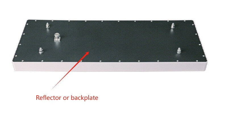
6. Ground plane: A ground plane is a conductive surface that acts as a reference point for the antenna. It is often used in antennas that require a ground connection, such as monopole or dipole antennas. The ground plane helps improve the antenna’s performance by providing a counterpoise or reflecting surface for the radiated signals.
7. Mounting hardware: Antennas require mounting hardware to secure them in place. This can include brackets, masts, poles, or other structures to hold the antenna in the desired position and orientation.
These components work together to enable the antenna to efficiently radiate or receive electromagnetic waves, allowing for the transmission or reception of radio signals.
How to design the antenna element?
Here are some general steps to design an antenna element:
1. Determine the operating frequency: The first step is to determine the frequency range over which the antenna will operate. This will dictate the size and shape of the antenna element.
2. Choose the antenna type: There are various types of antennas, such as dipole, monopole, patch, loop, and helical antennas. Each type has its own advantages and disadvantages, so choose the one that best suits your requirements.
While antenna design offers seemingly endless possibilities—with countless geometries to explore for specific performance goals—most general-purpose wireless applications rely on a handful of basic antenna elements. Some of the most common configurations you’ll encounter include:
- Dipole antennas: Simple and widely used, ideal for many broadband and omnidirectional applications.
- Monopole antennas: Similar to dipoles but require a ground plane, often used in mobile and base station setups.
- Wire-loop antennas: Compact and useful where space is limited, often employed in RFID and portable devices.
- Slot antennas: Suitable for higher-frequency applications and often integrated into surfaces.
- Microstrip (patch) antennas: Popular in modern wireless devices due to their low profile and ease of integration.
Beyond these, other specialized types—like helical or spiral antennas—can be selected for particular needs, such as circular polarization or compact form factors. By understanding these basic elements and their typical uses, you can more confidently select the antenna type that aligns with your project’s specific requirements.
3. Determine the physical dimensions: The physical dimensions of the antenna element are determined by the operating frequency and the desired radiation pattern. You can use mathematical equations, simulation software, or empirical methods to determine the dimensions.
4. Determine the feed point: The feed point is the location where the antenna is connected to the transmission line. The feed point affects the impedance matching and radiation pattern of the antenna. Again, you can use mathematical equations, simulation software, or empirical methods to determine the feed point.
5. Build a prototype: Once you have determined the dimensions and feed point, build a physical prototype of the antenna element. You can use conductive materials such as copper or aluminum for this purpose.
6. Measure and test: Measure the performance of the prototype using appropriate test equipment, such as a network analyzer or spectrum analyzer. Compare the measured results with the desired specifications and make any necessary adjustments to the design.

7. Iterate: Antenna design is an iterative process. You may need to repeat steps 4-6 multiple times to achieve the desired performance.
It’s important to note that designing an antenna element can be challenging and time-consuming. It often requires specialized knowledge and experience. If you are not familiar with antenna design, it is recommended to consult an expert or use pre-designed antenna elements that are commercially available.
In conclusion, antenna elements are the backbone of our connected world, allowing for seamless communication and data transfer. By understanding how they work and their various applications, we can appreciate the engineering marvels that keep us connected.
