 Skip to content

In the fast-evolving world of technology, Ultra-High Frequency (UHF) Radio Frequency Identification (RFID) systems have become indispensable across various industries, offering unparalleled efficiency and accuracy in tasks like inventory management and asset tracking. A critical factor in their effectiveness is the read range of the UHF RFID antenna. Understanding how to test this read range is essential for optimizing system performance. This article outlines nine essential steps to test the read range of a UHF RFID antenna, ensuring you get the most out of your RFID system.
Why One Antenna Design Doesn’t Fit Every RFID Application
It’s a common misconception that a single antenna design can meet the demands of every RFID application. In reality, each environment and use case presents unique challenges. For example, the antennas used in warehouse entry portals are engineered to cover wide areas and read multiple tags at once—a feature that would be excessive and inefficient in a retail setting focused on item-level inventory. On the flip side, compact antennas designed for handheld readers are ideal for close-up, targeted scans, but they lack the power and range necessary for applications like highway toll collection, where tags must be detected at greater distances and speeds.
In essence, factors such as reading distance, tag orientation, physical environment, and even the presence of metal or liquid all impact which antenna design will yield optimal performance. Selecting the right antenna ensures maximum efficiency, minimizes read errors, and helps tailor the RFID system to your specific operational needs.
Common Misconceptions About RFID Antenna Performance
Understanding how UHF RFID antennas work is crucial—not just for getting the most out of your system, but also for avoiding some common myths that can steer you wrong. Here are a couple of persistent misconceptions worth clearing up:
“Bigger Means Better”
It’s easy to assume that simply using a physically larger antenna guarantees superior read range or performance. However, this isn’t always true. In practice, a well-engineered compact antenna (think of designs from established brands like Laird or Times-7) can outperform a bulkier counterpart, depending on the application and environment. Factors such as gain, impedance matching, and installation placement often play a more significant role than sheer size alone.
“One Antenna Suits Every Application”
Another frequent pitfall is believing that a single antenna type will excel in all scenarios. The reality is, RFID environments vary widely—from the fast-paced demands of warehouse shipping portals to tightly packed retail clothing racks, or even highway toll booths. Each setup requires an antenna specifically tailored to its physical space, frequency band, and intended tag orientation. For instance, a circularly polarized antenna may be perfect for reading tags from many angles in logistics, while a linear design might be ideal for controlled, single-direction reads.
Being aware of these nuances ensures you select the right antenna solution, contributing to better accuracy and reliability in your RFID deployment.
Why Impedance Matching Matters in RFID Antenna Design
For any UHF RFID system, achieving optimal performance hinges significantly on proper impedance matching between your RFID antenna and reader. But why is this so crucial?
When the impedance of the antenna is matched to that of the reader’s transmission line—almost always 50 ohms—it allows for efficient transfer of energy. Without this harmony, a portion of the transmitted power is reflected back to the reader, which can lead to several problems:
- Shortened read range: The antenna can’t radiate the full available power, so tags farther away may go undetected.
- Unreliable system performance: Inconsistent reads and unpredictable losses can cause disruptions in scanning or tracking workflows.
- Risk of hardware issues: Persistent power reflection can stress or even damage sensitive reader circuitry.
To prevent these pitfalls, engineers take care to fine-tune antenna impedance using specialized equipment, ensuring that what leaves the reader travels smoothly to the antenna and out into the environment. This meticulous adjustment supports robust, reliable RFID operations—whether you’re managing inventory in a warehouse or tracking assets across a sprawling facility.
Step 1: Assemble the Necessary Equipment and Tools
Before you start testing, gather all the required equipment and Tools. You will need:
– A UHF RFID reader
– A UHF RFID antenna
– RFID tags compatible with your system
– A measuring tape or laser distance meter
– A laptop or computer with RFID software
– Power supply for the RFID reader
– Coaxial cable assembly to connect the RFID reader and antenna
– Mounting bracket for the antenna
– Other tools if necessary
Having all these items on hand will streamline the testing process and help you avoid unnecessary delays.
Step 2: Set Up the RFID Reader and Antenna
Setting up a UHF RFID reader and antenna is crucial for ensuring reliable and efficient RFID tag reading. This process involves mounting the antenna securely, connecting it to the RFID reader, and positioning the reader for optimal performance. Proper setup not only maximizes coverage and signal strength but also minimizes interference and potential signal loss. By following these steps meticulously, you can achieve a robust RFID system that meets your operational needs.
Below is a detailed guide to help you set up your UHF RFID reader and antenna effectively.
1. Mount the UHF RFID Antenna:
– Choose a stable surface for mounting the antenna, ensuring it is positioned to maximize coverage of the area where RFID tags will be read.
– Use appropriate mounting hardware (brackets, screws, etc.) to securely attach the antenna. Ensure it is firmly fixed to prevent any movement or vibrations that could affect performance.
2. Connect the Antenna to the RFID Reader:
– Identify the appropriate cables for connecting the antenna to the RFID reader. Typically, coaxial cables are used for this purpose.

– Connect one end of the coaxial cable to the antenna’s RF port.
– Connect the other end of the coaxial cable to the corresponding RF port on the RFID reader.
– Ensure both connections are tight and secure to prevent signal loss or interference.
3. Position the RFID Reader:
– Place the RFID reader in a convenient location that is easily accessible for monitoring, configuration, and maintenance.
– Ensure the reader is positioned within the effective range of the antenna for optimal performance.
– Consider environmental factors such as temperature, humidity, and potential sources of interference when choosing the location.
4. Power Up the RFID Reader:
– Connect the RFID reader to a power source using the provided power adapter or cable.
– Ensure the power connection is secure and the reader is receiving adequate power.
5. Verify Connections:
– Double-check all connections between the antenna, RFID reader, and power source.
– Look for any loose cables or connectors and tighten them as necessary.
6. Initial Testing:
– Power on the RFID reader and check for any status indicators or error messages.
– Use the reader’s software interface to verify that the antenna is properly connected and functioning.
7. Adjust Antenna Position if Necessary:
– If the initial testing indicates poor signal strength or read accuracy, adjust the antenna’s position and orientation.
– Ensure the antenna is aimed towards the area where RFID tags will be most frequently read.
By carefully following these steps, you will ensure that your UHF RFID reader and antenna are set up correctly, providing reliable and efficient RFID tag reading capabilities.
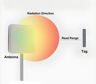
Understanding Antenna Gain and Its Impact on RFID Performance
Antenna gain plays a key role in how well your RFID system performs, directly affecting both your read range and coverage area. In simple terms, antenna gain describes how effectively an antenna focuses the radio signals it transmits or receives in a particular direction. Think of it like using a flashlight: a narrow, focused beam (high gain) shines farther, whereas a wide beam (low gain) lights up more area close by.
- High-gain antennas concentrate radio energy into a tight beam. This boosts the reader’s ability to identify tags at longer distances in that specific direction. High-gain options are well-suited for applications like toll collection or warehouse truck lanes, where you want to track tags passing through a defined area.
- Low-gain antennas spread the signal over a broader area but can’t reach as far. These are a great fit when you need to read tags scattered through a room or around large portals, such as in retail store entrances or supply rooms.
Your choice between high and low gain should match your environment and coverage needs: for focused, long-distance reads, go with higher gain; for broader, close-range coverage, opt for lower gain.
By understanding and selecting the appropriate antenna gain, you’ll maximize the accuracy and reliability of tag detection in your unique setup.
Step 3: Configure the RFID Software
Configuring the RFID software is a crucial step in setting up your RFID system. This software will allow you to monitor the read range, read rate, and other performance metrics of your RFID setup. Here’s how to go about it:
1. Install the RFID Software
– Obtain the Software: Download the RFID software from the manufacturer’s website or use the installation media provided with your RFID reader.
– System Requirements: Ensure your laptop or computer meets the system requirements specified by the software.
– Installation Process: Follow the on-screen instructions to install the software. This typically involves agreeing to the terms and conditions, choosing an installation directory, and waiting for the installation to complete.
2. Connect Your RFID Reader
– Physical Connection: Connect your RFID reader to your laptop or computer using the appropriate interface (USB, Ethernet, etc.).
– Power On: Ensure the RFID reader is powered on and properly connected to the antenna.
3. Launch the Software
– Open the Application: Find the RFID software application on your computer and launch it.
– Initial Setup: You may be prompted to complete an initial setup or configuration wizard. Follow the instructions provided.
4. Configure the RFID Reader
– Device Detection: The software should automatically detect the connected RFID reader. If not, navigate to the settings or device management section to manually add or detect the reader.
– Reader Settings: Configure the reader settings according to your needs. This may include setting the read power, frequency, and other parameters. Refer to the manufacturer’s instructions for specific details.
5. Configure the Antenna
– Antenna Settings: If the software allows, configure the antenna settings. This may include selecting the antenna port, adjusting the gain, and setting the polarization.
Understanding Polarization
Polarization refers to the orientation of electromagnetic waves as they travel from the antenna. You’ll typically have two options:
- Linear polarization: The waves oscillate in a single plane, either horizontally or vertically. This setup is ideal when both the reader and tag antennas share the same orientation, as it maximizes signal strength.
- Circular polarization: Here, the waves rotate as they propagate—either clockwise or counterclockwise. Circular polarization is useful when tag orientation varies, as it can read tags regardless of their position, though it can sometimes reduce maximum read range compared to perfectly aligned linear setups.
Matching the polarization of your reader and tag antennas is crucial. Misaligned polarization can cut your read range by up to 50%, so always double-check these settings for optimal performance.
– Antenna Placement: Ensure the antenna is properly placed and oriented for optimal performance.
6. Test the System
– Read Range Test: Use the software to perform a read range test. This will help you determine the effective range of your RFID system.
– Performance Metrics: Monitor other performance metrics such as read rate, tag detection, and signal strength.
7. Save and Apply Settings
– Save Configuration: Save the configuration settings within the software to ensure they are retained for future use.
– Apply Settings: Apply the settings to the RFID reader and antenna. This may involve restarting the system or reinitializing the reader.
8. Documentation and Support
– User Manual: Refer to the software’s user manual for detailed instructions and troubleshooting tips.
– Technical Support: If you encounter issues, contact the manufacturer’s technical support for assistance.
By carefully following these steps, you can ensure that your RFID software is properly configured, allowing you to effectively monitor and optimize the performance of your RFID system.
Step 4: Calibrate the RFID System
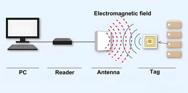
Calibrating an RFID system is a critical step in ensuring its optimal performance and accuracy. RFID (Radio Frequency Identification) technology relies on electromagnetic fields to automatically identify and track tags attached to objects. Proper calibration involves adjusting the system’s power levels, frequency, and other parameters according to the manufacturer’s guidelines. This process helps to minimize interference, maximize read range, and ensure reliable data capture.
To understand why calibration is so important, it helps to know the basics of how RFID systems operate. An RFID system is made up of three core components:
- RFID tags (transponders) attached to the items you want to track
- RFID readers (interrogators) that communicate with the tags
- Antennas on both the tags and readers, which send and receive the radio waves
These systems can operate across a range of frequencies—each with its own typical usage and antenna characteristics:
| Frequency Band | Approximate Range | Common Applications | Antenna Types |
| Low Frequency (LF) 125-134 kHz | A few centimeters | Animal tracking, access control | Larger coil antennas |
| High Frequency (HF) 13.56 MHz | Up to 1 meter | Payment cards, library books | Loop antennas |
| Ultra-High Frequency (UHF) 860-960 MHz | Up to 12 meters | Supply chain, retail inventory | Dipole or patch antennas |
| Microwave 2.45 GHz | Over 30 meters | Highway toll collection, vehicle tracking | Highly directional antennas |
The antenna, in particular, plays a crucial role as the interface between tag and reader—without proper calibration and antenna configuration, even advanced RFID systems may deliver inconsistent results.
Taking the time to understand your system’s frequency band and antenna setup ensures you’re able to fine-tune your calibration for the best possible performance. Whether you’re monitoring livestock, managing library loans, or tracking retail inventory, careful adjustment and calibration will help your RFID system operate smoothly and dependably. By carefully calibrating your RFID system, you can achieve consistent and accurate results, which are essential for applications ranging from inventory management to access control.
To calibrate the RFID system, follow these steps:
1. Review the manufacturer’s instructions: Read the user manual or documentation provided by the RFID system manufacturer. Look for specific instructions on how to calibrate the system.
2. Set the power level: Use the manufacturer’s recommended power level settings for your RFID system. This setting determines the strength of the RFID signal transmitted by the reader. Adjust the power level as needed to achieve the desired read range.
3. Set the frequency: Set the RFID reader to the appropriate frequency for your tags. Most RFID systems operate at either 125 kHz or 13.56 MHz. Check the documentation for your tags to find the correct frequency.
4. Adjust other parameters: Some RFID systems allow you to adjust additional parameters, such as the read time, read mode, or anti-collision settings. Review the manufacturer’s recommendations and adjust these parameters as needed.
5. Test the system: After calibrating the RFID system, test it to ensure that it is working correctly. Place a tag within the read range of the reader and verify that it is detected and read accurately.
6. Fine-tune the settings: If the system is not working as expected, you may need to fine-tune the settings. Adjust the power level, frequency, or other parameters and test the system again until it performs to your satisfaction.
By calibrating the RFID system before testing, you can ensure that it is set up correctly and will provide accurate results.
Step 5: Position the RFID Tags
Place the RFID tags at various distances from the antenna. Start with a short distance and gradually increase it. Make sure the tags are placed at different angles and orientations to test the antenna’s ability to read tags in various positions. Use the measuring tape or laser distance meter to ensure accurate placement.

You can also follow these steps:
1. Start by placing a tag about 1 meter away from the antenna. Place it flat on a surface, parallel to the ground.
2. Move the tag to different positions, such as upright, tilted, or upside down. Note if the antenna can still read the tag in each position.
3. Gradually increase the distance between the tag and the antenna, testing at each new distance.
4. Repeat the process with other tags, placing them at different distances and orientations.
5. Take note of the maximum distance at which the antenna can read each tag, as well as any positions or orientations where the antenna struggles to read the tag.
Step 6: Conduct Initial Testing
With the tags in place, start the RFID reader and monitor the read range using the RFID software. Record the distances at which the tags are successfully read. Repeat the process multiple times to ensure consistency and accuracy. Note any anomalies or inconsistencies in the readings.

Procedure
1. Setup and Calibration:
– Ensure the RFID reader is properly connected to the RFID software.
– Calibrate the reader according to the manufacturer’s instructions, if necessary.
2. Initial Read Range Test:
– Position the RFID tag at a known distance from the reader.
– Activate the RFID reader and observe the software for tag detection.
– Gradually increase the distance between the tag and the reader until the tag is no longer detected.
– Record the maximum distance at which the tag is read successfully.
3. Repetition for Accuracy:
– Repeat the read range test multiple times (e.g., 5-10 trials) for each tag.
– Ensure the environment remains consistent (e.g., same location, minimal interference).
4. Data Recording:
– Document the read distances for each trial in a table or spreadsheet.
– Note any variations in read distances across trials.
5. Identify Anomalies:
– Look for any inconsistencies or anomalies in the data, such as significant variations in read range.
– Record any environmental factors that might affect the readings (e.g., presence of metal objects, electronic interference).
6. Analyze Results:
– Calculate the average read range for each tag.
– Compare the average read ranges to the specified read range of the RFID system.
– Identify any tags that consistently fail to meet the expected performance.
Example Data Recording Table
| Trial | Tag ID | Distance (meters) | Successful Read (Y/N) |
|——-|——–|——————–|———————–|
| 1 | 001 | 1.0 | Y |
| 2 | 001 | 1.5 | Y |
| 3 | 001 | 2.0 | N |
| 4 | 002 | 1.0 | Y |
| 5 | 002 | 1.5 | Y |
| 6 | 002 | 2.0 | N |
| … | … | … | … |
Conclusion
– Summarize the findings from the initial testing.
– Highlight any tags that performed exceptionally well or poorly.
– Suggest potential adjustments or further tests needed based on the observed data.
By conducting thorough initial testing, you can ensure the reliability and accuracy of your RFID system and identify any areas that may require further optimization.
Step 7: Analyze the Results
When analyzing the results of your UHF RFID antenna tests, follow these steps to ensure a thorough evaluation:

1. Data Compilation:
– Gather all the data from your tests, including distances, angles, and environmental conditions.
– Organize the data in a structured format, such as a spreadsheet, to facilitate analysis.
2. Statistical Analysis:
– Calculate the average read range for different scenarios.
– Determine the standard deviation to understand the variability in your data.
– Identify any outliers that might indicate anomalies or errors during testing.
3. Pattern Recognition:
– Look for consistent patterns in the read range data. For example, does the read range decrease consistently with increased distance or certain angles?
– Note any specific conditions where the read range is significantly better or worse.
4. Environmental Factors:
– Assess the impact of environmental factors such as physical obstructions (walls, metal objects), electronic interference (Wi-Fi routers, other RFID systems), and ambient conditions (temperature, humidity).
– Compare the read ranges in different environments to identify any significant differences.
– Consider special cases:
- Metal-rich environments: Antenna performance may be reduced due to signal reflections. Testing and noting results in these settings can highlight the need for specialized antennas.
- Liquid-heavy settings: Read ranges might drop because of signal absorption. Document any notable differences here and consider if the antenna design is suitable.
- Dense reader environments: If multiple readers are present, interference can impact results. Directional antennas may help in this scenario, so note if directional or omnidirectional antennas were used.
5. Power Output and Regulatory Considerations:
– Note the power settings used during testing. Keep in mind that regulatory limits can affect maximum read range:
– North America (FCC): 4W EIRP
– Europe (ETSI): 2W ERP
– Japan: 250mW ERP
– If you conducted tests at different power levels, analyze how this impacted performance and ensure all testing complies with regional regulations.
6. Graphical Representation:
– Create graphs and charts to visually represent the data. For example, a scatter plot of read range vs. distance, or a bar chart comparing read ranges in different environments.
– Use heat maps to visualize read range performance across different angles and distances.
7. Root Cause Analysis:
– Investigate any unexpected results or anomalies. Consider factors such as antenna orientation, tag positioning, and power settings.
– Conduct additional tests if necessary to isolate and understand the cause of these anomalies.
8. Documentation:
– Document your findings comprehensively, including any identified patterns, trends, and potential issues.
– Summarize the key takeaways and insights from the analysis.
9. Recommendations:
– Based on your analysis, provide recommendations for optimizing the UHF RFID antenna setup. This could include changes in antenna placement, adjustments to reader settings, or environmental modifications.
– Suggest any further tests or studies that could help in fine-tuning the system.
By thoroughly analyzing the results, you can gain a clear understanding of the effective read range of your UHF RFID antenna and identify any factors that may be impacting its performance. This will help in making informed decisions to optimize the RFID system for your specific application.
Best Practices for Optimizing UHF RFID Antenna Performance
To really get the most from your RFID system, it’s essential to consider not just the data, but also the physical setup and installation environment. Here are some key best practices to ensure optimal antenna performance:
- Maintain Adequate Separation: Ensure there is a minimum distance between multiple antennas to prevent signal interference and cross-talk.
- Mounting Surface Matters: Pay attention to the mounting surfaces. Antennas installed on or near metal surfaces can experience detuning or reduced performance. Use spacers or special mounting brackets if necessary.
- Polarization Alignment: Align the antenna’s polarization with the expected orientation of the tags. Mismatched polarization can significantly reduce read range.
- Quality Cabling: Use high-quality cables and connectors to minimize signal loss between the reader and the antenna.
- Site Survey: Conduct a site survey before permanent installation to identify potential sources of interference or physical obstacles. This helps in selecting the ideal mounting locations and orientations.
- Environmental Assessment: Be mindful of environmental changes such as temperature, humidity, and the presence of electronic devices, as these can influence system performance.
Step 8: Optimize the System
After analyzing the results, we can make several adjustments to optimize the RFID system:

1. Reposition the antenna: Based on the results, it appears that the antenna is not positioned optimally. We will try repositioning the antenna to improve the read range. We can experiment with different heights and angles to find the best position.
2. Adjust the power levels: The power levels may be too low, resulting in a shorter read range. We can increase the power levels and conduct additional tests to see if this improves the read range.
3. Change the orientation of the tags: The orientation of the tags can affect the read range. We can experiment with different orientations to find the best position for the tags.
4. Test different tag types: Different tag types may have different read ranges. We can test different tag types to see if there are any improvements in read range.
5. Test different tag placements: The placement of the tags on the objects may affect the read range. We can experiment with different placements to find the best position for the tags.
6. Test different frequencies: RFID systems operate at different frequencies, such as low frequency (LF), high frequency (HF), and ultra-high frequency (UHF). We can test different frequencies to see if there are any improvements in read range.
By making these adjustments and conducting additional tests, we can optimize the RFID system and improve the read range.
Installation Checklist for Reliable Performance
For a quick recap—whether you’re optimizing an existing setup or planning a new one, keep these points in mind:
- Double-check antenna positioning and mounting surfaces.
- Confirm correct polarization alignment with your tags.
- Use proper cabling and minimize cable lengths where possible.
- Perform a thorough site survey to anticipate and address sources of interference.
With these best practices and systematic optimizations, you’ll set your RFID system up for reliable, high-performance operation across a range of applications.
Step 9: Document the Findings
Finally, document your findings in a detailed report. Include information on the equipment used, the test setup, the calibration settings, and the results of the tests. This documentation will serve as a valuable reference for future testing and troubleshooting.

Here’s a structured approach to documenting your findings in a detailed report:
1. Title Page
– Title: Clearly state the purpose of the report.
– Author(s): List the names of the individuals who conducted the tests.
– Date: Include the date when the report was completed.
2. Table of Contents
– Provide a list of sections and subsections with page numbers for easy navigation.
3. Executive Summary
– Purpose: Briefly state the objective of the testing.
– Key Findings: Highlight the most important results.
– Conclusions: Summarize the main conclusions drawn from the tests.
4. Introduction
– Background: Provide context and background information.
– Objective: Clearly state the objectives of the testing.
– Scope: Define the scope and limitations of the tests.
5. Equipment and Materials
– List of Equipment: Detail all equipment used, including model numbers and specifications.
– Materials: Describe any materials used during the testing process.
6. Test Setup
– Diagram: Include diagrams or photos of the test setup.
– Description: Provide a detailed description of how the equipment was set up.
– Environment: Describe the testing environment, including any relevant conditions like temperature, humidity, etc.
7. Calibration Settings
– Calibration Procedures**: Describe the calibration procedures followed.
– Settings: Document all calibration settings used during the tests.
– Verification: Include any verification steps taken to ensure calibration accuracy.
8. Methodology
– Procedures: Detail the step-by-step procedures followed during the tests.
– Variables: List the variables that were controlled and monitored.
– Data Collection: Explain how data was collected, including any software or tools used.
9. Results
– Data Presentation: Present the raw data in tables, charts, or graphs.
– Analysis: Provide a detailed analysis of the data.
– Comparisons: Compare the results with expected outcomes or standards.
10. Discussion
– Interpretation: Interpret the results and discuss their implications.
– Anomalies: Address any anomalies or unexpected results.
– Limitations: Discuss any limitations encountered during the testing.
11. Conclusions
– Summary: Summarize the key findings.
– Implications: Discuss the broader implications of the results.
– Recommendations: Provide any recommendations for future testing or improvements.
This structured approach ensures that your report is comprehensive, easy to navigate, and provides all necessary information for future reference and troubleshooting.
Summary
Testing the read range of a UHF RFID antenna is a critical step in ensuring the optimal performance of your RFID system. By following these nine steps, you can accurately determine the effective read range and make any necessary adjustments to optimize the system. From assembling the necessary equipment to documenting your findings, each step plays a crucial role in achieving accurate and reliable results. With a well-tested and optimized RFID system, you can improve efficiency, accuracy, and overall performance in your applications.
Testing and Validation
Before full deployment, thorough testing is essential:
- Laboratory Performance Verification: Begin by validating the system in a controlled environment. This allows you to identify and resolve any issues before moving to a live setting.
- Pilot Implementation in Actual Environment: Test the RFID system in the intended operational environment. This step helps uncover real-world factors—such as interference or unexpected material effects—that can impact performance.
- Performance Optimization Based on Real-World Results: Use the data collected during pilot testing to fine-tune system parameters. Adjust antenna placement, reader settings, and environmental controls as needed to optimize read range and reliability.
By combining structured testing procedures with staged validation and optimization, you’ll ensure your RFID deployment delivers consistent, dependable results both in the lab and out in the field.