 Skip to content
In the quest for optimal wireless communication and signal transmission, understanding and perfecting antenna radiation patterns is paramount. The cURL Too many subrequests., a specialized environment designed to eliminate reflections and external noises, provides the ideal setting for such meticulous testing. This article delves into the step-by-step process of testing antenna radiation patterns in an anechoic chamber, highlighting the significance of each phase and the critical considerations to ensure accurate and reliable results.
What are the Antenna Radiation Patterns?
Antenna radiation patterns describe how an antenna radiates energy into space or receives energy from space. These patterns are typically represented graphically in two or three dimensions and are crucial for understanding the performance and behavior of an antenna in different directions. Here are some key aspects and types of antenna radiation patterns:
Key Aspects of Radiation Patterns
1. Main Lobe: The region in the radiation pattern where the antenna radiates or receives the most power. This is typically the direction in which the antenna is intended to operate.
2. Side Lobes: These are smaller lobes around the main lobe where the antenna radiates or receives energy. Side lobes are usually undesirable because they can cause interference and reduce the antenna’s efficiency.
3. Back Lobe: The lobe that is opposite the main lobe. It represents the radiation in the opposite direction of the main beam and is usually minimized in directional antennas.
4. Beamwidth: The angular width of the main lobe, usually measured between the points where the power drops to half its maximum value (3 dB points). Beamwidth is an important parameter for understanding the directivity of the antenna.
5. Nulls: Points in the radiation pattern where the radiation intensity is zero or minimal. These are directions in which the antenna does not radiate or receive energy.
Types of Radiation Patterns
1. Isotropic Pattern: An idealized pattern where the antenna radiates equally in all directions. An isotropic antenna is a theoretical construct used as a reference for measuring the gain of real antennas.
2. Omnidirectional Pattern: A real-world pattern where the antenna radiates equally in all horizontal directions. Vertical radiation may vary. Common examples include whip antennas and dipole antennas in the horizontal plane.
3. Directional Pattern: The antenna radiates more power in specific directions. These patterns are used to focus energy in a particular direction, which can increase range and reduce interference. Examples include Yagi-Uda antennas, parabolic dish antennas, and horn antennas.
4. Dipole Pattern: Typically has a figure-eight shape in the plane perpendicular to the dipole. Dipole antennas are common and have a relatively simple radiation pattern.
5. Cardioid Pattern: Resembles a heart shape and is often used in microphone and antenna arrays to achieve directionality with minimal back lobe radiation.
Visualization
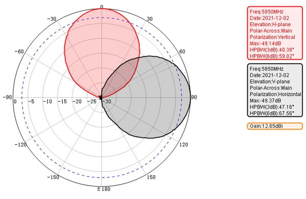
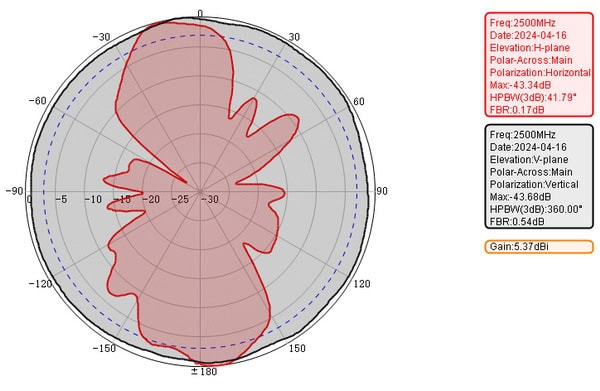
– Polar Plot: A common way to represent radiation patterns, showing the relative strength of the radiation at various angles in a 2D plane.
– 3D Plot: Provides a more comprehensive view of the radiation pattern in three dimensions, showing how the antenna radiates in all directions.
Applications
– Communication Systems: Understanding radiation patterns helps in designing antennas for specific communication needs, such as satellite communication, broadcasting, and cellular networks.
– Radar Systems: Directional antennas with narrow beamwidths are used to focus energy on specific targets.
– Wireless Networks: Omnidirectional antennas are often used in Wi-Fi routers to provide coverage in all directions.
Understanding and analyzing antenna radiation patterns is essential for optimizing antenna performance and ensuring effective communication in various applications.
The Role of the Electromagnetic Anechoic Chamber
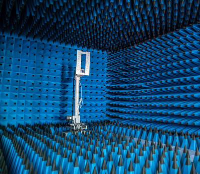
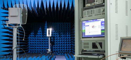
An electromagnetic anechoic chamber is a specialized facility designed to absorb reflections of electromagnetic waves, providing an environment that simulates free space conditions. These shielded test cells are essential for creating an RF-quiet environment, allowing for precise and repeatable measurements without external interference or unwanted reflections.
Anechoic chambers come in various configurations, including near-field and far-field antenna measurement chambers, each tailored to meet specific testing requirements. They play a vital role in a wide range of applications, such as automotive and telecom wireless technology, aerospace and defense radome assessments, radar cross-section (RCS) testing, and more. By eliminating electromagnetic noise and echoes, these chambers make it possible to evaluate the true performance of antennas and electronic devices under controlled conditions, ensuring accurate and reliable results.These chambers are crucial in various fields, particularly in the testing and development of electronic devices and systems. Here are some key roles and applications of electromagnetic anechoic chambers:
1. Electromagnetic Compatibility (EMC) Testing:
– Radiated Emissions Testing: Ensures that electronic devices do not emit electromagnetic interference (EMI) that could affect other devices.
– Radiated Immunity Testing: Assesses a device’s ability to operate correctly when exposed to electromagnetic interference from external sources.
2. Antenna Testing:
– Antenna Performance: Evaluates parameters such as gain, radiation pattern, and efficiency in a controlled, reflection-free environment.
– Antenna Calibration: Provides a controlled setting for precise calibration of antennas.
3. Radar and Communication Systems:
– Radar Cross-Section (RCS) Measurements: Measures the detectability of objects (such as aircraft or ships) by radar systems.
– Communication System Testing: Tests the performance of communication devices and systems, ensuring they operate correctly without interference.
4. Wireless Device Testing:
– Mobile Phones and Wi-Fi Devices: Evaluates the performance of wireless communication devices, including signal strength, data transfer rates, and overall reliability.
– IoT Devices: Tests Internet of Things (IoT) devices to ensure they function correctly in various electromagnetic environments.
cURL Too many subrequests.
cURL Too many subrequests.
cURL Too many subrequests.
cURL Too many subrequests.
cURL Too many subrequests.
cURL Too many subrequests.
cURL Too many subrequests.
cURL Too many subrequests.
cURL Too many subrequests.
cURL Too many subrequests.
cURL Too many subrequests.
cURL Too many subrequests.
cURL Too many subrequests.
cURL Too many subrequests.
cURL Too many subrequests.
cURL Too many subrequests.
- cURL Too many subrequests. cURL Too many subrequests.
- cURL Too many subrequests. Often used for lower frequencies, ferrite tiles are ceramic-based panels mounted on the chamber walls. They’re especially effective in the MHz to low GHz range, complementing foam absorbers for broadband coverage.
- Specialty Absorbers: For specific testing needs (such as high-power applications or unusual frequency bands), chambers might incorporate wedge, hybrid, or multilayer absorbers. Some are tailored for ultra-wideband performance, while others are engineered for durability under high power loads.
Shielding Materials
- Conductive Wall Linings: The chamber itself is typically constructed from steel or other conductive materials that act as a Faraday cage. This keeps external electromagnetic fields out, ensuring repeatable results inside.
- RF Shielded Doors: Entryways are designed with robust seals and layers of conductive material. These prevent leaks that could compromise test accuracy.
- Gasket Materials: Where panels or doors meet, conductive gaskets ensure continuous shielding, closing any gaps that might allow interference.
By combining these absorptive and shielding components, anechoic chambers can simulate a “quiet zone,” free from echoes and interference—ideal conditions for precise, repeatable testing of antennas, wireless devices, and more.
Common Features and Accessories for Anechoic Chambers
Anechoic chambers are much more than four foam-lined walls and a quiet air conditioner. To ensure precise testing and versatility, these specialized environments are often equipped with an array of features and accessories tailored to specific needs:
- Absorptive Materials: High-performance absorbers, such as carbon-loaded foam panels or ferrite tiles, minimize internal reflections. These materials are critical for simulating free-space conditions and are often selected based on the frequency range of interest.
- Shielded Enclosures: Robust shielding—often incorporating thick metallic layers—prevents external radio frequencies from contaminating measurements and ensures a controlled test environment.
- Positioning Systems: Rotary and linear positioners enable precise orientation and movement of devices and antennas during tests. Motorized towers or robotic arms may also be used to achieve repeatable, automated measurement sweeps.
- Reference Antennas and Measurement Probes: A selection of calibrated antennas and broadband measurement probes allows for thorough characterization of devices under test across different frequencies and polarizations.
- Controllers and Data Acquisition Hardware: Advanced controllers and logging systems coordinate equipment, record test data, and automate measurement sequences for accuracy and efficiency.
- RF Shielded Doors and Access Panels: Specialized doors and panels maintain the chamber’s isolation, allowing for easy access while minimizing RF leakage.
- Environmental Controls: Features such as temperature and humidity regulation are essential for sensitive electronics, especially in aerospace, automotive, or medical device testing.
- Modular and Adaptable Structures: Many chambers feature modular absorber panels or expandable construction, enabling customization for unique applications like vehicle or radar system testing.
- Test Fixtures and Model Towers: These accessories hold antennas or prototypes in precise positions, supporting everything from handheld electronics to large-scale aerospace components.
By incorporating these features and accessories, anechoic chambers support a diverse range of applications while maintaining the accuracy and repeatability essential for rigorous electromagnetic testing.
How Shielded Test Cells Enable RF Quiet Environments
Shielded test cells, along with specialized antenna measurement chambers—whether designed for near-field or far-field evaluations—create an environment isolated from external radio frequency (RF) interference. By surrounding the test area with conductive materials and RF-absorptive linings, these enclosures block unwanted electromagnetic signals from both inside and outside the chamber.
This controlled, “RF quiet” space is crucial across a spectrum of applications:
- Automotive and Wireless Communications: Ensures precise, repeatable measurements for modern cars’ electronic systems and telecom devices.
- Aerospace and Defense: Supports demanding tests like radome performance and radar cross-section (RCS) analysis, where even minor electromagnetic leakage can skew results.
- Emerging Technologies: Assists researchers and engineers in developing and evaluating new wireless standards or advanced communication protocols without interference.
cURL Too many subrequests.
cURL Too many subrequests.
cURL Too many subrequests.
cURL Too many subrequests.
cURL Too many subrequests.
cURL Too many subrequests.
cURL Too many subrequests.
cURL Too many subrequests.
cURL Too many subrequests.
cURL Too many subrequests.
- cURL Too many subrequests. cURL Too many subrequests.
- cURL Too many subrequests. cURL Too many subrequests.
- cURL Too many subrequests. cURL Too many subrequests.
- Reference Antennas and Measurement Probes: cURL Too many subrequests.
- cURL Too many subrequests. cURL Too many subrequests.
Measurement Process
1. Conducting the Measurements:
– The measurement process involves rotating the antenna and capturing data at different angles. This is typically done in both azimuth (horizontal) and elevation (vertical) planes. The data collected includes parameters such as gain, directivity, and beamwidth, which are essential for characterizing the antenna’s performance.
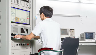
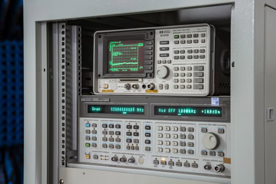
2. Using Network Analyzers and Spectrum Analyzers:
– Network analyzers and spectrum analyzers are commonly used to measure the antenna’s response. Network analyzers measure parameters like return loss and impedance, while spectrum analyzers help in identifying the frequency components of the emitted signal. These instruments provide valuable insights into the antenna’s efficiency and performance.
3. Data Analysis and Interpretation:
– Once the measurements are complete, the data is analyzed to generate radiation patterns. This involves plotting the measured values on polar or Cartesian coordinates to visualize the antenna’s performance. Advanced software tools are often used to facilitate this process, providing detailed insights into the antenna’s behavior across different frequencies and angles.
Types of Measurement Systems
Depending on the testing objectives and the frequency ranges involved, various measurement systems may be employed:
- Compact Ranges: Utilize precision reflectors to simulate far-field conditions in a smaller space, ideal for high-frequency or space-constrained applications.
- Single-Probe vs. Multi-Probe Systems: Single-probe systems offer flexibility for diverse test setups, while multi-probe arrays can capture full radiation patterns more efficiently.
- Hybrid Systems: Combine features of both near-field and far-field measurement techniques for comprehensive antenna characterization.
Environmental and Safety Considerations
- Shielded Chambers and Doors: Maintain electromagnetic isolation from the external environment to ensure accuracy and safety.
- RF Safety Protocols: Ensure personnel safety during high-power measurements, with features like interlocked doors and warning systems.
- Temperature and Humidity Control: Some chambers include environmental controls to account for test conditions that could influence measurement accuracy.
By integrating these components and processes, the measurement setup in an anechoic chamber is finely tuned to deliver precise, repeatable, and reliable antenna performance data—laying the groundwork for the comprehensive analysis that follows.
Key Considerations
1. Environmental Factors:
– While the anechoic chamber is designed to eliminate external interferences, it’s essential to consider factors such as temperature and humidity, as they can impact the measurements. Maintaining a controlled environment ensures the accuracy and reliability of the results.
2. Antenna Mounting and Support Structures:
– The materials used for mounting and supporting the antenna can affect the measurements. Non-conductive and low-reflective materials are preferred to minimize any interference with the antenna’s radiation pattern. Properly designed support structures ensure that the antenna is securely positioned without affecting its performance.
3. Frequency Range and Bandwidth:
– Different antennas operate at various frequency ranges, and it’s crucial to ensure that the measurement system is capable of accurately capturing data across the entire bandwidth. This involves using appropriate filters and calibration techniques to cover the desired frequency range.Measurement setups commonly support a span from 0 MHz up to 40,000 MHz (40 GHz), accommodating everything from low-frequency communications to cutting-edge millimeter wave applications. Ensuring your equipment and procedures can handle the required spectrum is essential for obtaining precise and reliable results.
Advanced Techniques
1. Near-Field to Far-Field Transformation:
– In some cases, it may not be feasible to measure the antenna’s radiation pattern directly in the far-field region. Near-field to far-field transformation techniques can be used to extrapolate the far-field pattern from near-field measurements. This involves complex mathematical algorithms and precise measurements to ensure accurate results.
– Specialized measurement chambers—such as near-field or far-field antenna measurement chambers—provide the necessary RF-quiet environment for these advanced testing applications. These chambers enable precise and repeatable antenna assessments for a wide variety of industries, including automotive and telecom wireless technology, as well as aerospace and defense applications like radome and radar cross-section (RCS) testing. By minimizing external interference, these controlled environments are essential for both near-field data collection and reliable transformation to the far-field pattern.
2. 3D Radiation Pattern Measurements:
– Advanced testing setups allow for 3D radiation pattern measurements, providing a comprehensive view of the antenna’s performance in all directions. This involves capturing data at multiple planes and combining them to generate a 3D representation of the radiation pattern.
3. Active Testing of Antennas:
– Active testing involves evaluating the performance of an antenna when it is part of a complete system, including the transmitter and receiver. This type of testing focuses on parameters like Effective Isotropic Radiated Power (EIRP), Total Radiated Power (TRP), and Total Isotropic Sensitivity (TIS).
Effective Isotropic Radiated Power (EIRP) Measurement
– EIRP is a critical parameter in active antenna testing, representing the power radiated by the antenna in the direction of maximum gain. It is measured by considering the transmitter power and the antenna gain. Accurate EIRP measurements are crucial for ensuring compliance with regulatory standards and optimizing system performance.
Total Radiated Power (TRP) Measurement
– TRP measures the total power radiated by the antenna in all directions. This parameter is important for understanding the overall efficiency of the antenna system. TRP measurements are typically performed in an anechoic chamber to eliminate external interferences and reflections.
cURL Too many subrequests.
cURL Too many subrequests.
cURL Too many subrequests.
cURL Too many subrequests.
cURL Too many subrequests.
cURL Too many subrequests.
cURL Too many subrequests.
cURL Too many subrequests.
cURL Too many subrequests.