 Skip to content

In recent times, ultra-wideband (UWB) technology has become increasingly popular across multiple sectors, thanks to its exceptional accuracy and adaptability. For anyone interested in understanding the workings of UWB antennas and their unique features, this article provides a comprehensive overview, covering fundamental definitions and real-world applications.
A UWB antenna is a specialized antenna designed to operate across a wide range of frequencies, typically spanning several gigahertz. Its unique geometry and dimensions allow it to handle ultra-short pulses, making it ideal for high-accuracy positioning, sensing, and short-range communication applications.
To gain a comprehensive understanding of UWB antennas, it’s essential to first familiarize yourself with the fundamentals of UWB technology and its function within communication systems.
What is UWB?
Ultra-wideband (UWB) is a wireless communication protocol designed for short-range, high-bandwidth transmission across a wide frequency spectrum. Unlike conventional narrowband technologies that use specific frequency ranges, UWB utilizes a broad bandwidth, enabling data transmission with minimal interference. It is particularly recognized for its exceptional tracking accuracy, often within centimeters, and its low energy consumption, making it ideal for applications such as smart tags, smartphones, and automotive systems.
What is a UWB Antenna Used For?
UWB (Ultra-Wideband) antennas are used for a variety of applications due to their ability to transmit data over a wide frequency range with high precision. Here are some key uses:
1. Data Transmission: UWB antennas facilitate high-speed wireless communication, making them suitable for applications requiring rapid data transfer.
2. Positioning and Location Identification: UWB technology is widely employed in positioning systems, providing accurate location data for both indoor and outdoor environments. This is particularly useful in navigation systems and for locating assets.

3. Sensing and Tracking: UWB antennas are used in systems that require real-time tracking of objects or individuals, such as in logistics and supply chain management.
4. Automotive Applications: In the automotive industry, UWB antennas are utilized for keyless entry systems, allowing for secure and convenient vehicle access.

5. Consumer Electronics: UWB technology is integrated into various consumer devices for features like proximity detection, smart home automation, and enhanced connectivity between devices.
6. Medical Applications: UWB antennas can be used in healthcare for monitoring patients and tracking medical equipment within facilities.
7. Industrial Applications: In warehouses and manufacturing environments, UWB antennas assist in asset tracking, inventory management, and improving operational efficiency.
Overall, UWB antennas are essential for systems that require high precision, low latency, and the ability to operate in environments with high levels of interference. Their versatility makes them valuable across multiple industries.
How Does the UWB Antenna Work?
Ultra-Wideband (UWB) antennas operate by utilizing a technique that transmits information through extremely short pulses across a broad spectrum of frequencies, typically ranging from 3.1 GHz to 10.6 GHz. This wide frequency range allows UWB systems to achieve high data rates and precise ranging capabilities, making them ideal for applications like location tracking, radar, and high-speed wireless communication.
Key Features of UWB Antennas:
1. Pulse Transmission: UWB antennas emit very short pulses (on the order of nanoseconds), which results in a wide bandwidth. This characteristic allows UWB systems to transmit data at high speeds and to determine the time-of-flight of signals for accurate distance measurements.
2. Broad Frequency Range: The antenna is designed to operate efficiently over a wide frequency range, which helps in minimizing interference from other wireless systems. This is particularly beneficial in environments with many overlapping signals, such as urban areas.
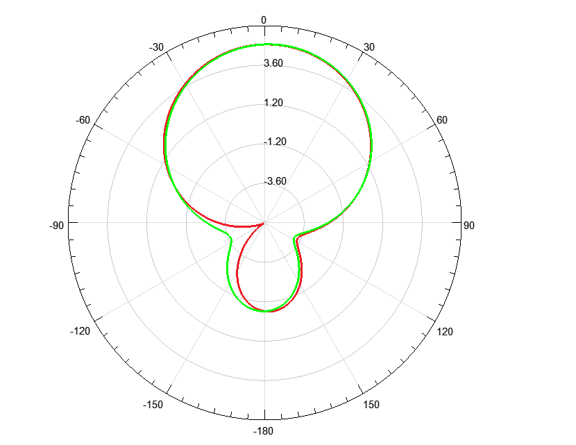
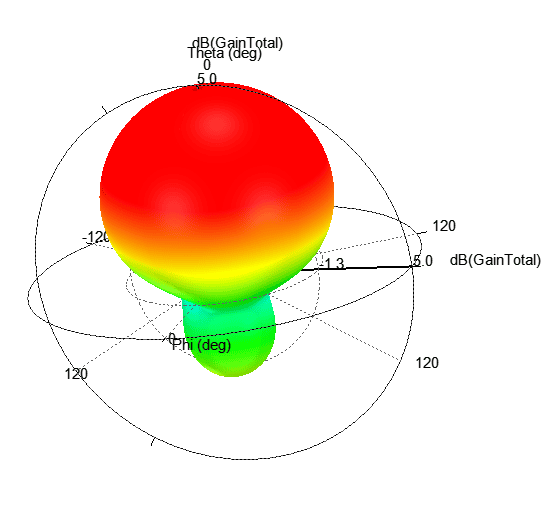
3. Radiation Pattern: The design of UWB antennas ensures that they maintain a consistent and efficient radiation pattern across the wide frequency range. This is essential for achieving reliable communication and accurate localization.
4. Low Power Consumption: UWB technology is known for its low power requirements, which makes it suitable for battery-operated devices. The short pulses mean that UWB systems can transmit data without needing to use high power, thus extending the life of the devices.
5. Interference Resilience: Due to its wideband nature, UWB is less susceptible to interference from narrowband systems. This resilience is particularly useful in crowded radio frequency environments.
6. Multipath Mitigation: UWB signals can take advantage of multipath propagation, where signals bounce off surfaces and arrive at the receiver via different paths. This characteristic can be used to enhance location accuracy and signal robustness.
Efficiency and Power Considerations
A core principle in UWB antenna design is maximizing efficiency—ensuring as much of the energy provided to the antenna as possible is radiated, not lost. This is especially critical because UWB devices operate at much lower transmit power levels (often limited to -41.3 dBm/MHz) compared to technologies like Bluetooth and Wi-Fi, which utilize higher power for longer-range communication. As UWB operates at higher frequencies, path loss increases, making it even more important to minimize additional antenna losses to maintain effective performance.
Optimizing Radiation Patterns
The radiation pattern of a UWB antenna is pivotal for reliable operation. While some applications might benefit from directional antennas with high gain in specific orientations, most UWB systems rely on omnidirectional antennas. Omnidirectional designs radiate power equally in all directions, which not only ensures consistent coverage but also helps in meeting regulatory requirements for effective isotropic radiated power (EIRP). Keeping the maximum peak gain within limits is vital for certification, especially since UWB devices operate close to their maximum allowable output.
Minimizing Nulls and Considering Placement
Nulls—directions in which the antenna radiates little or no energy—are another key design consideration. Poorly controlled nulls can result in coverage gaps or weak signal areas, potentially degrading performance. The placement and orientation of the antenna within a device, as well as nearby materials (like a user’s hand on a gaming mouse), can significantly affect these patterns. Simulation tools are often used to anticipate these effects, allowing engineers to optimize antenna performance even before building hardware prototypes.
Polarization and Alignment
UWB antennas also require careful attention to polarization. Mismatched polarization between transmitting and receiving antennas can result in significant signal loss, sometimes up to 10–15 dB, which can be enough to disrupt communication entirely in challenging environments like large open spaces or conference rooms. Ensuring optimal polarization alignment maximizes signal reception and minimizes loss.
In summary, UWB antennas are designed to effectively transmit ultra-short pulses over a wide frequency range, enabling accurate localization and high-speed data transmission while being resilient to interference and minimizing power consumption.
How Can Designers Maximize Antenna Efficiency at Low Power Levels?
Given the inherently low transmit power of UWB systems—far lower than Bluetooth or Wi-Fi—efficiency becomes the linchpin of effective antenna design. Every microwatt counts. To ensure that as much input energy as possible is actually radiated (rather than lost as heat or reflected back), designers must carefully engineer for maximum efficiency across the ultra-wide frequency range.
A few strategies are particularly important:
- Optimized Materials and Geometry: cURL Too many subrequests.
- Impedance Matching: cURL Too many subrequests.
- Broadband Performance: cURL Too many subrequests.
- cURL Too many subrequests. cURL Too many subrequests.
- cURL Too many subrequests. cURL Too many subrequests.
cURL Too many subrequests.
cURL Too many subrequests.
cURL Too many subrequests.
cURL Too many subrequests.
cURL Too many subrequests.
cURL Too many subrequests.
cURL Too many subrequests.
cURL Too many subrequests.
cURL Too many subrequests.
cURL Too many subrequests.
cURL Too many subrequests.
cURL Too many subrequests.
The placement and use environment of the antenna also play a big role. Consider a device such as a wireless gaming mouse with an internal UWB antenna. The antenna’s radiation pattern will initially be evaluated in free space, but the moment it is enclosed in the mouse’s housing—and, even more so, when a user’s hand covers the mouse—the surrounding materials absorb or alter electromagnetic waves. This changes where nulls fall in the pattern, and can impact gain and efficiency.
To offset these challenges, engineers use advanced simulation tools during design and prototyping. Software like CST Microwave Studio, HFSS, or KeySight EMPro allows designers to model how enclosures, circuit boards, and even human tissue (like a user’s hand) influence radiation patterns. Through these virtual tests, designers can optimize antenna placement and structure to minimize detrimental nulls, ensuring robust UWB performance in real-world use cases.
Leveraging Simulation Software for UWB Antenna Optimization
Simulation software plays a vital role in the design process of UWB antennas, especially when tailoring them to fit within unique device enclosures or meet specific operating scenarios. Rather than relying solely on physical prototypes—which can be both time-consuming and costly—engineers can use advanced simulation tools like CST Microwave Studio, ANSYS HFSS, or Keysight EMPro to model the performance of a UWB antenna within a given device.
By simulating various enclosure shapes, materials, or even the interaction with nearby components, these platforms allow designers to:
- Visualize and adjust the antenna’s radiation patterns in real time.
- Predict signal performance in complex environments, helping to identify and mitigate sources of interference or undesirable reflections.
- Assess the impact of device materials—such as plastics, metals, or composites—on antenna efficiency and bandwidth.
- Optimize antenna placement within the device to achieve the best trade-off between space constraints and wireless performance.
- Rapidly evaluate the effect of different design iterations without needing to fabricate multiple physical models.
This approach streamlines development and ensures that the final UWB antenna design delivers optimum performance for the device’s specific use case, whether that’s a compact medical tag, an automotive sensor, or a consumer wearable.
What are the Benefits of a UWB Antenna?
Ultra-Wideband (UWB) antennas offer several benefits, making them increasingly popular in various applications, particularly in wireless communications, positioning, and radar systems. Here are some of the key benefits of UWB antennas:
1. High Data Rates: UWB technology can support very high data transmission rates, making it suitable for applications that require fast data transfer, such as multimedia streaming and high-speed wireless communication.

2. Low Power Consumption: UWB systems operate at low power levels, which makes them energy-efficient. This is particularly advantageous for battery-powered devices and IoT applications where power conservation is critical.
3. Precise Positioning and Localization: UWB antennas provide high-resolution ranging and positioning capabilities, often within centimeters. This makes them ideal for applications in indoor navigation, asset tracking, and location-based services.
4. Robustness to Interference: UWB operates over a wide frequency spectrum, which allows it to be less susceptible to interference from other wireless signals. This characteristic makes UWB suitable for environments with a high density of wireless devices.
5. Multipath Resistance: UWB signals can effectively mitigate multipath propagation issues, where signals reflect off surfaces and cause distortion. This results in improved signal clarity and reliability, especially in complex environments.
6. Wide Bandwidth: The wide bandwidth of UWB antennas allows for greater channel capacity and improved frequency diversity. This can lead to enhanced performance in crowded frequency bands.
7. Compact Size: UWB antennas can be designed to be small and compact, making them suitable for integration into portable devices and wearables without significant space requirements.
8. Cost-Effective Implementation: As the technology matures, the cost of UWB components and systems is decreasing, making it a more economically viable option for various applications.
9. Versatile Applications: UWB antennas can be used in a wide range of applications, including automotive (for collision avoidance and parking assistance), healthcare (for patient tracking), industrial automation, and smart home devices.
10. Regulatory Compliance: UWB technology is often compliant with various regulatory standards, allowing for deployment in multiple regions without significant modifications.
Overall, UWB antennas provide a combination of high performance, efficiency, and versatility that is beneficial for modern wireless communication and localization applications.
FCC Regulations on UWB Antenna Power and Design Implications
When designing UWB antennas, one of the most important regulatory considerations is compliance with the FCC’s strict limits on effective isotropic radiated power (EIRP). The FCC mandates that UWB devices operating within the 3.1 GHz to 10.6 GHz frequency band must not exceed an EIRP of –41.3 dBm per 1 MHz. This requirement is far more stringent than those applied to many conventional wireless technologies, such as Bluetooth or Wi-Fi, which operate well below their maximum power thresholds during certification.
This low EIRP ceiling serves two main purposes:
- Minimizing Interference: By capping radiated power, UWB devices can coexist with other users of the radio spectrum without causing disruption.
- Promoting Spectral Efficiency: The regulation encourages designers to optimize system performance through efficient modulation and robust signal processing, rather than relying on higher output power.
Because every decibel matters for UWB compliance, antenna engineers must carefully balance gain and directivity. Omnidirectional antenna designs are typically favored, as they help keep the peak gain below regulatory thresholds, reducing the risk of failing certification tests and ensuring reliable, widespread signal coverage.
Designers also often employ techniques such as power back-off, precision tuning, and advanced materials to both maximize performance and ensure compliance. Ultimately, these regulatory requirements drive the development of more sophisticated and thoughtful UWB antenna designs, supporting efficient wireless communication in dense, multi-user environments.
What is the Range of UWB Antennas?
Ultra-Wideband (UWB) antennas are designed to operate over a wide frequency range, typically from 3.1 GHz to 10.6 GHz. This wide bandwidth allows UWB systems to transmit data at high speeds and enables precise location tracking and radar applications.
The effective range of UWB antennas can vary based on several factors, including:
1. Power Output: UWB systems are typically limited in power output to avoid interference with other communication systems, which impacts range.
2. Environment: UWB signals can penetrate walls and other obstacles better than higher frequency signals, but they can still be affected by materials like metal and dense concrete.
3. Antenna Design: The specific design of the UWB antenna (e.g., gain, radiation pattern) can influence its range and performance.
4. Receiver Sensitivity: The sensitivity of the receiving device also plays a crucial role in determining the effective communication range.
In general, UWB systems can achieve ranges of up to 30 meters (about 100 feet) in indoor environments and potentially longer in open outdoor environments, though the actual range can vary widely depending on the factors mentioned above.
cURL Too many subrequests.
cURL Too many subrequests.
cURL Too many subrequests.
cURL Too many subrequests.
cURL Too many subrequests.
cURL Too many subrequests.
cURL Too many subrequests.
cURL Too many subrequests.
cURL Too many subrequests.
cURL Too many subrequests.
cURL Too many subrequests.
cURL Too many subrequests.
cURL Too many subrequests.
cURL Too many subrequests.
cURL Too many subrequests.
cURL Too many subrequests.
cURL Too many subrequests.
cURL Too many subrequests.
cURL Too many subrequests.
– The choice of polarization affects the antenna’s radiation pattern, gain, and overall performance. For instance, mismatched polarization between transmitting and receiving antennas can lead to significant signal loss.In fact, polarization mismatch can result in losses of up to 10 to 15 dB, which may be enough to disrupt or even kill the link—especially in open spaces or large conference rooms where there isn’t sufficient reflection to boost the received energy. Due to the limited power typically transmitted in UWB systems, optimal alignment of polarization between antennas is especially important to maximize signal reception and minimize these losses.
– In UWB applications, where signals can span multiple frequencies simultaneously, the polarization characteristics can influence the bandwidth and efficiency of the antenna.
cURL Too many subrequests.
– When designing UWB antennas, engineers must consider the desired polarization in relation to the intended application. This may involve trade-offs between size, gain, and bandwidth.
– The antenna’s physical structure, such as its shape and material, can influence its polarization characteristics. Techniques such as using specific feed mechanisms or incorporating elements like parasitic structures can help achieve the desired polarization.
4. Measurement and Testing:
– Characterizing the polarization of UWB antennas involves measuring their radiation patterns and gain across the frequency spectrum. This ensures that the antenna performs as intended for the specific polarization mode.
In summary, polarization is a vital aspect of UWB antenna design, impacting performance across various applications. Selecting the appropriate polarization type and understanding its implications can lead to improved communication efficiency and reliability.
Ultra-wideband Antenna Types
Ultra-wideband (UWB) antennas come in various types, each designed for specific applications and performance characteristics. Here are some common types of UWB antennas:
1. Omni-Directional Antennas: These antennas radiate energy uniformly in all directions in a horizontal plane. They are useful for applications where coverage in all directions is needed, such as wireless sensor networks and short-range communication systems.
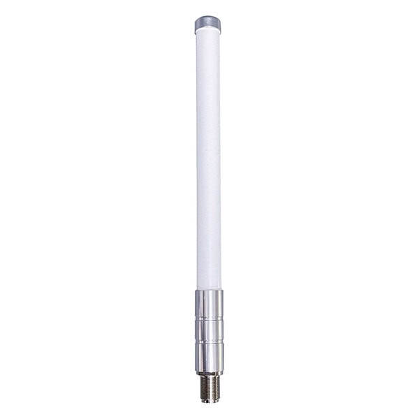
When considering UWB (ultra-wideband) applications, the antenna’s radiation pattern is a critical aspect of design. Omnidirectional antennas are often preferred in UWB radio systems because they maximize output power in all directions, helping to avoid the pitfalls of high gain in only specific orientations. This is especially important because certification standards, such as those set by the FCC, limit the effective isotropic radiated power (EIRP) to strict thresholds (e.g., -41.3 dBm per 1 MHz of bandwidth in the 3.1 to 10.6 GHz range). By keeping the maximum peak gain in check, omnidirectional antennas make it easier to meet these regulatory limits and ensure consistent performance.
Radiation Pattern and Null Considerations
Antenna radiation patterns can contain “nulls”—specific directions where radiated power drops to a minimum or even zero. In UWB antenna design, minimizing these nulls is crucial to avoid coverage gaps and to maintain reliable communication, especially in dynamic environments or when the antenna is integrated into complex housings (like inside a gaming mouse or under a user’s hand). Simulation tools can be invaluable for predicting how enclosure materials, shapes, and even nearby objects like a human hand will affect the radiation pattern, allowing designers to optimize placement and structure before prototyping.
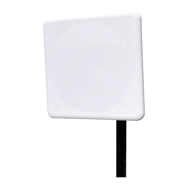
2. Panel Antennas: These are flat, rectangular antennas that can be either directional or omni-directional. They are often used in indoor environments for wireless communications, providing a compact form factor and ease of installation.
3. Patch Antennas: A type of planar antenna, patch antennas are typically low-profile and can be designed for specific frequency ranges. They are often used in applications like RFID and wireless communication due to their compact size and ease of integration.
4. Dipole Antennas: Simple and effective, dipole antennas can be used in UWB applications. They are often used in portable devices and can be designed to cover the UWB frequency range.
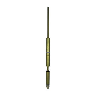
5. Monopole Antennas: Similar to dipole antennas but typically mounted on a ground plane, monopole antennas can be used in UWB applications where space is limited.
6. Log-Periodic Antennas: These antennas can operate over a wide frequency range and are often used in applications requiring multi-band capabilities. They are characterized by their periodic structure, which allows them to maintain performance across a broad spectrum.
7. Horn Antennas: These antennas are used for applications requiring high gain and directivity. They are often employed in testing and measurement scenarios due to their ability to provide a controlled radiation pattern.

8. Slot Antennas: These antennas consist of a slot cut into a conductive surface, and they can be designed to operate over a wide frequency range. They are often used in compact applications and can be integrated into circuit boards.
9. Fractal Antennas: Utilizing fractal geometries, these antennas can achieve multi-band performance in a compact form factor. They are useful in applications where size constraints are critical.
Directional vs. Omnidirectional Choices
While directional antennas (like panel and horn antennas) offer high gain in targeted directions, they may exhibit suboptimal performance in other orientations, which can limit coverage in dynamic or multipath environments. Omnidirectional antennas, by contrast, provide more uniform coverage, reducing the chance of dead spots and easing compliance with strict power regulations.
Application-Driven Selection
Each type of UWB antenna has its advantages and is selected based on the specific requirements of the application, including range, directionality, size, and frequency response.Additionally, careful attention to radiation patterns, null minimization, and regulatory constraints ensures optimal performance and reliability in real-world deployments.
Modular and Flexible UWB Antenna Architectures
When it comes to integrating UWB antennas into modern devices, designers have a wealth of modular and flexible architectural options to choose from—each offering unique trade-offs in performance, size, integration ease, and cost.
Chip Antennas:
These tiny, off-the-shelf components have become increasingly popular for their plug-and-play modularity. Chip antennas simplify the integration process and help speed up product development. However, because they come in standardized formats, customization for specific applications may be limited.
PCB-Based Antennas:
A staple in the world of UWB design, PCB antennas are created by patterning traces directly onto the circuit board itself. This approach is highly efficient in terms of space since it makes use of existing board real estate. PCB antennas are cost-effective and can be precisely tailored to match a device’s frequency and polarization needs, making them a favorite for many compact wireless gadgets.
Sheet-Metal Antennas:
Borrowed from Bluetooth and Wi-Fi device design, sheet-metal antennas are now making their way into UWB applications. These antennas are typically stamped or formed from metal sheets, providing exceptional flexibility for custom shapes and orientations. They’re especially handy for odd-shaped housings or challenging placements where PCB antennas might not fit, and their 3D construction can support specialized polarization requirements.
Laser Direct Structuring (LDS) and 3D-Printed Antennas:
For truly complex surfaces or when squeezing antennas into tight, non-planar spaces, LDS antennas offer a high-tech solution. This technique involves using a laser to “draw” antenna patterns directly onto plastic housings or other surfaces, effectively turning the device’s casing into a functional antenna. Similarly, 3D-printed antenna designs are rapidly evolving, enabling integration into intricate device geometries for lightweight and ultra-compact products.
By carefully selecting from or combining these modular antenna architectures—chip, PCB, sheet-metal, or LDS/3D-printed—engineers can optimize their UWB solutions for a wide spectrum of devices and environments, from wearables and smartphones to industrial automation systems.
Evolving Ecosystem and Future Trends in UWB Antenna Technology
The ultra-wideband antenna industry is rapidly transforming, ushering in innovative solutions that make UWB implementation more accessible and robust than ever before. This evolution benefits from a dynamic marketplace, where both established and emerging technology providers—think Murata, Taoglas, and Abracon—offer a continually expanding selection of UWB antenna products.
Greater Modularity and Design Flexibility
One of the most significant trends is the move toward highly modular antenna formats. Commercial off-the-shelf UWB chip antennas are gaining popularity thanks to their compact design and plug-and-play integration, which lets developers easily retrofit or quickly prototype devices. While chip antennas streamline the process, they offer more limited options for deep customization or unique form factors.
Innovations in Antenna Architectures
At the same time, PCB-based UWB antennas remain a go-to for many designers. By etching antenna patterns directly onto circuit boards, these solutions make efficient use of space and enable cost-effective mass production, all while offering sufficient flexibility for fine-tuning performance parameters.
cURL Too many subrequests.
cURL Too many subrequests.
cURL Too many subrequests.
cURL Too many subrequests.
cURL Too many subrequests.
- cURL Too many subrequests.
- cURL Too many subrequests.
- cURL Too many subrequests.
- cURL Too many subrequests.
cURL Too many subrequests.
cURL Too many subrequests.
cURL Too many subrequests.