 Skip to content
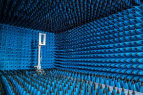
Imagine a room where electromagnetic waves are completely absorbed, creating an eerily interference-free environment. This is the essence of an anechoic chamber, a space meticulously designed to eliminate any reflections of electromagnetic waves. These chambers are crucial for the precise testing and measurement of RF antennas, allowing researchers to conduct accurate and uncontaminated experiments.
An cURL Too many subrequests. is a specialized testing environment meticulously designed to create a free-field condition for precise electromagnetic wave measurements. By eliminating reflections and external electromagnetic interference, it ensures an ideal setting for accurate testing of RF antennas. This controlled environment is essential for evaluating the performance and characteristics of antennas, free from the distortions caused by external noise or signal reflections.
Understanding the intricacies of anechoic chambers is vital for applications involving the testing of RF antennas and the behavior of electromagnetic waves.
What is an electromagnetic anechoic chamber called?
An electromagnetic anechoic chamber is often referred to simply as an “anechoic chamber.” These chambers are specially designed to absorb reflections of electromagnetic waves, typically using radio frequency (RF) absorbing material on the walls, ceiling, and floor. This creates an environment that simulates free space, devoid of external electromagnetic interference and internal reflections, making it ideal for testing and measuring antennas, radar systems, and various other electromagnetic devices.
What is the chamber for antenna testing?
A chamber for antenna testing, often referred to as an anechoic chamber, is a specialized facility designed to provide a controlled environment for testing antennas and other electromagnetic devices. These chambers are engineered to simulate free-space conditions by minimizing reflections and external electromagnetic interference, ensuring accurate and repeatable measurements.
Key features of an anechoic chamber include:
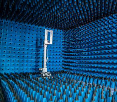
1. Absorptive Material: The walls, ceiling, and floor of the chamber are lined with radio-frequency (RF) absorptive material, typically made of foam pyramids or wedges impregnated with carbon. These materials absorb electromagnetic waves, preventing reflections that could interfere with measurements.
2. Shielding: The chamber is often constructed with metallic shielding to block external RF signals, creating a quiet electromagnetic environment. This shielding ensures that the only signals present are those intentionally introduced for testing.
3. Controlled Environment: Anechoic chambers provide a controlled environment where temperature, humidity, and other environmental factors can be regulated to ensure consistent and reliable test conditions.
4. Positioning Systems: Many anechoic chambers are equipped with precise positioning systems that can rotate and move the antenna under test. This allows for comprehensive testing of the antenna’s radiation pattern in three dimensions.
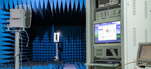
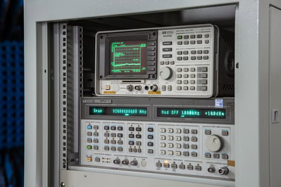
5. Measurement Equipment: The chamber is equipped with various measurement instruments, such as network analyzers, spectrum analyzers, and signal generators, to facilitate the testing and characterization of antennas.
Anechoic chambers are used for a variety of tests, including:
– Radiation Pattern Measurement: Determining the directional characteristics of an antenna’s radiation.
– Gain Measurement: Assessing the antenna’s ability to direct energy in a specific direction.
– Impedance Testing: Evaluating the antenna’s impedance characteristics to ensure proper matching with transmission lines.
– EMC Testing: Ensuring that electronic devices comply with electromagnetic compatibility (EMC) standards by measuring emissions and susceptibility.
Overall, anechoic chambers are essential tools in the design, development, and testing of antennas, ensuring that they perform as expected in real-world applications.
What is an electromagnetic anechoic chamber used for?
An electromagnetic anechoic chamber is a specialized facility designed to completely absorb reflections of electromagnetic waves, thereby simulating a free-space environment. These chambers are used for a variety of applications, including:
1. Electromagnetic Compatibility (EMC) Testing:** To ensure that electronic devices do not emit excessive electromagnetic interference (EMI) and are not susceptible to EMI from other devices.
2. Antenna Testing: To measure the performance of antennas, including their radiation patterns, gain, and efficiency, without interference from external signals or reflections.
3. Radar Cross-Section (RCS) Measurements: To determine how detectable an object is by radar by measuring the amount of electromagnetic energy it reflects.
4. Wireless Communication Testing: To evaluate the performance of wireless communication devices and systems, such as mobile phones, Wi-Fi routers, and other RF devices, in a controlled environment.
5. Research and Development: To conduct experiments and develop new technologies in a controlled electromagnetic environment, ensuring accuracy and repeatability of results.
6. Calibration of Instruments: To calibrate measurement instruments that are sensitive to electromagnetic fields, ensuring their accuracy in real-world applications.
The walls, ceiling, and floor of an anechoic chamber are lined with materials that absorb electromagnetic waves, such as pyramidal foam absorbers or ferrite tiles, to prevent reflections and external electromagnetic noise from interfering with the tests.
What are typical applications of high-precision anechoic and hemi-anechoic chambers?
High-precision anechoic and hemi-anechoic chambers serve a key role in a variety of acoustic and audio measurement applications, allowing professionals to conduct highly sensitive and repeatable experiments without interference from external sounds or internal echoes.
Common uses of these specialized chambers include:
Microphone Calibration:
Laboratories use these chambers for both primary and secondary calibration of microphones, enabling precise measurement of frequency response, directivity, and accuracy. This includes free-field and substitution methods to ensure microphones meet rigorous standards.
Speaker Design and Research:
Engineers and researchers rely on the controlled acoustic environment to evaluate loudspeaker performance. This includes detailed analysis of sound power output, frequency response, physical design optimization, and distortion measurements.
Acoustic Science and Research:
Anechoic chambers are indispensable in academic research, such as doctoral projects, studies in ultrasound technology, and virtual acoustics. Scientists generate auralizations of spaces—from modern concert halls to busy city streets—to improve architectural acoustics or develop new audio technologies.
Product Certification and Compliance:
cURL Too many subrequests.
cURL Too many subrequests.
cURL Too many subrequests.
cURL Too many subrequests.
cURL Too many subrequests.
cURL Too many subrequests.
cURL Too many subrequests.
cURL Too many subrequests.
cURL Too many subrequests.
cURL Too many subrequests. cURL Too many subrequests.
cURL Too many subrequests. cURL Too many subrequests.
cURL Too many subrequests. cURL Too many subrequests.
cURL Too many subrequests.
cURL Too many subrequests.
cURL Too many subrequests.
cURL Too many subrequests.
1. RF Absorbers:
– Pyramidal Foam Absorbers: The walls, ceiling, and sometimes the floor of the chamber are lined with pyramidal-shaped absorbers made from carbon-loaded foam or ferrite materials. These absorbers are designed to attenuate electromagnetic waves by gradually converting their energy into heat as the waves penetrate the material.
– Absorption Mechanism: The pyramidal shape increases the surface area and ensures that incoming electromagnetic waves are absorbed progressively, minimizing reflections and echoes within the chamber.
2. Shielding:
– Metallic Shielding: The entire chamber is often encased in a metallic shield, typically made from copper or aluminum, to block external electromagnetic interference (EMI). This creates a controlled environment free from unwanted RF signals.
– Sealed Doors and Windows: Specially designed doors and windows maintain the integrity of the shielding when closed, ensuring that no external electromagnetic waves enter the chamber.
3. Isolation from External Interference:
– Thick, Dense Walls: The chamber walls are constructed to block external electromagnetic noise, providing an isolated environment for accurate testing.
– Vibration Isolation: The chamber is often built on vibration-isolated foundations to prevent external vibrations from affecting sensitive measurements.
Design Considerations
– Non-parallel Surfaces: The chamber may feature non-parallel surfaces to minimize standing waves and ensure that electromagnetic waves are absorbed rather than reflected between parallel walls.
– Size and Shape: The size and shape of the chamber are carefully designed to suit specific testing requirements, ensuring optimal performance for the frequencies and types of devices being tested.
Applications
– Antenna Testing: Electromagnetic anechoic chambers are extensively used for testing antennas, allowing engineers to measure parameters such as radiation patterns, gain, and efficiency without interference from external signals or reflections.
– Wireless Device Testing: These chambers are also used to test wireless devices, including smartphones, routers, and IoT devices, ensuring that they perform reliably in real-world conditions.
– Radar and Communication Systems: The controlled environment is ideal for testing radar systems, satellite communication equipment, and other RF devices, providing accurate and reliable data.
Conclusion
By eliminating reflections and external electromagnetic interference, an electromagnetic anechoic chamber provides a highly controlled environment for precise testing and measurement of antennas and other electronic devices. This ensures that the results are accurate, reliable, and free from external variables, making it an indispensable tool in the development and testing of modern wireless technology.
How does a cable floor system work in a fully anechoic chamber?
In fully anechoic chambers, especially those designed for both electromagnetic and acoustic testing, maintaining the chamber’s absorption properties from every angle is crucial—including the floor. That’s where the cable floor system comes into play.
Structure and Design
Unlike traditional solid floors, a cable floor system suspends a series of tightly tensioned stainless steel cables in a crisscross pattern above the chamber’s floor absorbers, typically at a height of about four inches above the absorber tips. This design allows engineers and test subjects to walk safely inside the chamber while ensuring that the absorbers underneath do their job uninterrupted.
Key Features:
Minimal Obstruction: The cables are spaced evenly (often about 50mm apart) to provide enough strength for movement yet remain largely transparent to electromagnetic and acoustic waves. This means the floor doesn’t introduce unwanted reflections or compromise the chamber’s performance.
Debris Management: Beneath the cable matrix, there’s usually a fine nylon net that acts as a safety catch—preventing small items from falling deep between the absorbers and becoming difficult to retrieve.
Tension and Stability: The cables are anchored at both ends—one end using turnbuckles for precise tension adjustments and the other with coil springs to maintain even stress and flexibility. This results in a stable, gently deforming surface that can handle foot traffic without damaging the absorbers below.
In Summary
The cable floor system offers a practical and effective solution for fully anechoic chambers, enabling safe access for personnel and equipment while fully preserving the chamber’s reflection-free environment.
What are the benefits of an electromagnetic anechoic chamber?
An electromagnetic anechoic chamber offers several benefits, particularly in the fields of electromagnetic compatibility (EMC) testing, antenna design, and radio frequency (RF) measurements. Here are some of the key advantages:
1. Controlled Environment: The chamber provides a controlled environment free from external electromagnetic interference (EMI), allowing for accurate and repeatable measurements.
2. Minimized Reflections: The walls of an anechoic chamber are lined with RF-absorbing material that minimizes reflections of electromagnetic waves. This simulates a free-space environment, which is ideal for testing and measurements.
3. Enhanced Accuracy: By eliminating external noise and reflections, the chamber enables highly accurate measurements of electromagnetic fields, antenna patterns, and device emissions.
4. Compliance Testing: Anechoic chambers are essential for EMC testing to ensure that electronic devices comply with international standards and regulations. This includes tests for emissions, immunity, and susceptibility.
5. Antenna Characterization: The chamber is used to measure antenna radiation patterns, gain, efficiency, and other parameters without interference from external sources or reflections.
6. Product Development: Engineers can use the chamber to test and refine the electromagnetic performance of new products, leading to better design and functionality.
7. Safety: The chamber provides a safe environment for testing high-power RF devices, as it contains the electromagnetic energy within the chamber and prevents it from affecting the surrounding area.
8. Versatility: Anechoic chambers can be used for a wide range of frequencies, from radio to microwave and even millimeter-wave frequencies, making them versatile tools for various applications.
9. Isolation: The chamber isolates the device under test (DUT) from external electromagnetic environments, which is crucial for sensitive measurements and for testing devices in their operational electromagnetic environment.
10. Research and Development: They are invaluable in academic and industrial research for studying electromagnetic wave propagation, material properties, and other phenomena related to electromagnetism.
cURL Too many subrequests.
cURL Too many subrequests.
cURL Too many subrequests.
cURL Too many subrequests.
cURL Too many subrequests.
cURL Too many subrequests.
cURL Too many subrequests.
cURL Too many subrequests.
cURL Too many subrequests.
cURL Too many subrequests.
cURL Too many subrequests.
cURL Too many subrequests.
cURL Too many subrequests.
cURL Too many subrequests.
cURL Too many subrequests.
cURL Too many subrequests.
cURL Too many subrequests.
cURL Too many subrequests.
cURL Too many subrequests.
– RF shielding gaskets: To ensure a tight seal that prevents electromagnetic leakage.
– Waveguide-beyond-cutoff designs: For any necessary openings, such as for cables or ventilation.
By combining these materials and construction techniques, an electromagnetic anechoic chamber can effectively simulate a free-space environment, which is crucial for testing and measuring the performance of various electronic and electromagnetic devices.
Flooring Systems in Anechoic Chambers
The design of the floor in an anechoic chamber is an essential consideration, as it must balance accessibility for people and equipment with the need to absorb electromagnetic energy and eliminate unwanted reflections. There are several flooring systems commonly used, each tailored to support different testing requirements while maintaining the chamber’s non-reflective characteristics.
1. Grid-Based and Raised Floors
Many chambers employ a grid or modular raised flooring system. These structures allow personnel and test equipment to move throughout the chamber while minimizing compromise to the underlying RF-absorbing materials, such as pyramidal foam wedges or tiles. The modular grids are usually made of non-reflective or acoustically transparent materials, ensuring they do not introduce significant electromagnetic or acoustic reflections.
2. Cable Floors
For fully anechoic environments, a tensioned cable floor is frequently used. This involves a series of stainless steel cables strung tightly in a crisscross pattern, typically several centimeters above the absorbing layer. The purpose is twofold:
- The cable spacing allows electromagnetic waves to pass through with minimal obstruction, preserving the chamber’s absorption properties.
- The floor supports both technicians and equipment, while a secondary catch net—typically made of nylon—is installed beneath to prevent accidental loss of tools or small objects between the wedges.
3. Retractable and Removable Floors
Some advanced chambers incorporate retractable or completely removable floor segments. These systems can expose the absorptive material fully during high-precision measurements, removing any structural surfaces that could cause reflections. Once testing is complete, the flooring can be restored for safe movement and setup inside the chamber.
4. Specialized Absorbing Floor Tiles and Conductive Surfaces
Depending on testing protocols, some chambers make use of specialized absorbing tiles on the floor to maintain a consistent non-reflective environment, while others employ conductive flooring to ensure proper grounding, especially for sensitive EMC testing.
These flooring solutions are critical because even a small reflective surface—such as a standard floor—can undermine the high-precision measurements that anechoic chambers are designed for. By integrating absorptive and structurally supportive designs, these systems help to maintain the chamber’s free-space simulation while allowing users to safely and efficiently operate within the space.
What does an electromagnetic anechoic chamber consist of?
An electromagnetic anechoic chamber is a specialized facility designed to completely absorb reflections of electromagnetic waves and provide a controlled environment for testing and measuring electromagnetic emissions and immunity. It typically consists of the following components:
1. Radio Absorbing Material (RAM): The interior surfaces of the chamber are lined with materials that absorb electromagnetic waves, such as pyramidal or wedge-shaped foam absorbers coated with conductive materials like carbon. These materials prevent reflections and simulate an open-space environment.Depending on the frequency range, the absorbers may be made from foam, ferrite tiles, or fiberglass, with careful attention paid to the low-frequency cutoff requirements. Often, an interior non-reflective cable floor system is installed above the floor wedges, sometimes with a nylon catch net below for additional safety and protection.
2. Shielded Enclosure: The chamber is usually constructed with metal walls, often steel or aluminum, to form a Faraday cage. This shielding prevents external electromagnetic interference from entering the chamber and ensures that the internal signals do not escape.For enhanced performance, some designs use double or single wall and ceiling panel construction, sometimes with an additional layer of copper or aluminum mesh to boost shielding effectiveness.
3. Test Equipment: The chamber is equipped with various instruments for generating, receiving, and measuring electromagnetic signals. This includes signal generators, antennas, spectrum analyzers, and other diagnostic tools essential for comprehensive testing.
4. Turntable and Positioners: To facilitate comprehensive testing, the chamber may have a motorized turntable or positioners that can rotate and move the device under test (DUT) to different orientations and positions.
5. Structural and Acoustic Features: The frame and structural components are typically made from non-conductive materials such as wood or fiberglass to avoid interfering with electromagnetic properties. Some chambers incorporate vibration isolators below the floor (such as floating floor systems) to minimize the transmission of external vibrations and noise, ensuring test accuracy.
6. Control Room: Adjacent to the chamber, there is usually a control room where operators can monitor and control the testing process without being exposed to high levels of electromagnetic radiation.
7. Ventilation and Lighting: The chamber is equipped with non-metallic ventilation ducts and lighting systems that do not interfere with the electromagnetic environment. These are designed to maintain the chamber’s anechoic properties.Waveguide-beyond-cutoff vents are often used to allow air movement while blocking electromagnetic waves, and lighting is selected or shielded to minimize unwanted emissions.
8. Access Doors: Specially designed doors with electromagnetic seals are used to maintain the integrity of the shielded enclosure when personnel or equipment need to enter or exit the chamber.
These doors may feature RF shielding gaskets and wedge acoustic design for maximum effectiveness.
9. Grounding System: A robust grounding system is essential to ensure safety and to prevent unwanted electromagnetic interference.
10. Data Acquisition Systems: These systems collect and analyze data from the tests conducted within the chamber, providing detailed information on the electromagnetic characteristics of the DUT.
11. Cable Ports and Access Points: Circular cable ports allow cables to enter and exit the chamber without compromising RF integrity. All entry points, including those for ventilation and cables, are carefully engineered—often using waveguide-beyond-cutoff construction—to maintain shielding and prevent leakage.
By integrating these carefully engineered materials, features, and systems, an electromagnetic anechoic chamber is able to provide a reliable, interference-free environment essential for accurate electromagnetic testing and research.
By combining these elements, an electromagnetic anechoic chamber provides a controlled, interference-free environment that is essential for accurate and reliable electromagnetic testing and research.
How much does an electromagnetic anechoic chamber cost?
The cost of an electromagnetic anechoic chamber can vary significantly based on several factors, including its size, the frequency range it is designed to handle, the level of shielding, the quality of the absorptive materials used, and any additional features or customization. Here are some general price ranges:
1. Small Chambers: These are typically used for testing smaller devices or components and might cost anywhere from $50,000 to $200,000.
2. Medium Chambers: These are suitable for testing larger devices or multiple components and could range from $200,000 to $1 million.
3. Large Chambers: These are designed for testing large systems or vehicles and can cost from $1 million to several million dollars.
4. Specialized Chambers: Chambers designed for very high frequencies, specific applications, or with advanced features (such as automated testing equipment) can also be quite expensive, often exceeding several million dollars.
Beyond these basics, there are a variety of optional features that can add both capability and cost to a chamber installation. For example:
- Floor Grating: Essential for chambers intended to support heavy equipment or vehicles, providing both structural stability and accessibility.
- cURL Too many subrequests. cURL Too many subrequests.
- cURL Too many subrequests. cURL Too many subrequests.
- cURL Too many subrequests. cURL Too many subrequests.
- cURL Too many subrequests. cURL Too many subrequests.
- cURL Too many subrequests. cURL Too many subrequests.
cURL Too many subrequests.
cURL Too many subrequests.
cURL Too many subrequests.
cURL Too many subrequests.

cURL Too many subrequests.
cURL Too many subrequests.
cURL Too many subrequests.
cURL Too many subrequests.
cURL Too many subrequests.
1. Electromagnetic Exposure:
– Reduced Exposure: Anechoic chambers are designed to absorb electromagnetic waves, which means that the levels of electromagnetic fields (EMFs) inside the chamber are generally lower than in typical environments. This reduced exposure can be beneficial for individuals who are sensitive to EMFs.
– Safety Standards: The levels of EMFs in anechoic chambers are usually well within international safety standards for human exposure, such as those set by the International Commission on Non-Ionizing Radiation Protection (ICNIRP) and the Federal Communications Commission (FCC).
2. Psychological and Sensory Effects:
– Sensory Deprivation: Anechoic chambers are also designed to absorb sound waves, creating an environment with extremely low levels of ambient noise. This can lead to a form of sensory deprivation, which some people may find disorienting or uncomfortable. Prolonged exposure to such an environment can cause auditory hallucinations, a heightened awareness of bodily sounds (such as heartbeat and breathing), and a sense of isolation.
– Disorientation: The lack of acoustic and visual cues can cause disorientation or a feeling of imbalance in some individuals. This is because our brains rely on these cues to navigate and maintain spatial awareness.
3. Psychological Stress:
– Isolation: The combination of electromagnetic and acoustic isolation can create a feeling of being cut off from the outside world, which might induce stress or anxiety in some individuals.
– Claustrophobia: Some people might experience claustrophobia due to the enclosed nature of the chamber.
4. Health and Safety Considerations:
– Short-Term Exposure: For most people, short-term exposure to an anechoic chamber is generally safe and does not pose significant health risks.
– Long-Term Exposure: There is limited research on the long-term effects of spending extended periods in an anechoic chamber. However, given the potential for sensory deprivation and psychological stress, it is advisable to limit exposure duration and ensure that individuals are monitored for any adverse effects.
In summary, while electromagnetic anechoic chambers are generally safe for short-term human exposure, they can induce sensory deprivation and psychological stress due to their unique environmental conditions. It is important to monitor individuals for any signs of discomfort or disorientation and to limit exposure duration as necessary.
cURL Too many subrequests.
Anechoic chambers are crucial tools for precise measurement and testing in the field of electromagnetic research, particularly for antennas. These specially designed rooms absorb electromagnetic waves, preventing reflections and external interference. This controlled environment allows for accurate testing and characterization of antenna performance, ensuring reliable and advanced technological outcomes.