 Skip to content
Are you looking for ways to optimize your microwave communication system or enhance the efficiency of your radar technology? One critical component that could make a substantial difference is the orthomode transducer (OMT). Understanding the role and benefits of an OMT can provide you with the insights needed to significantly improve your system’s performance.
In the realm of microwave communication systems, the orthomode transducer is an essential device that facilitates the separation and combination of orthogonal polarizations. This capability is particularly advantageous in applications requiring high-frequency signal transmission and reception, such as satellite communications, radar systems, and advanced wireless networks.
An orthomode transducer (OMT) is a crucial component in microwave communication systems, designed to separate or combine two orthogonally polarized signals within waveguide setups. By efficiently handling polarized signals, it enhances signal clarity and overall system performance, making it essential for applications like satellite communications and radar systems.
Now, let’s delve deeper into how this versatile device works, the advantages and applications.
What is an orthomode transducer (OMT) waveguide?
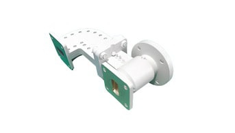
An orthomode transducer (OMT) waveguide is a specialized device used in microwave and radio frequency (RF) systems to separate or combine signals with different polarizations. It is commonly used in antenna systems, particularly in satellite communications and radar applications, where the efficient handling of dual-polarized signals is essential.
Key Functions
1. Polarization Separation/Combination:
Separation: An OMT can separate two orthogonal polarizations (typically vertical and horizontal) from a single input waveguide into two distinct output waveguides. This is useful when a single antenna is used to receive or transmit two different signals simultaneously.
Combination: Conversely, it can combine two orthogonally polarized signals into a single waveguide, allowing a single antenna to handle both signals.
2. Isolation:
OMTs provide high isolation between the two orthogonal polarizations, ensuring minimal interference and cross-talk between the signals.
Structure
An OMT typically consists of:
Input Port: Where the combined signal enters or exits.
Output Ports: Two ports for the separated orthogonal polarized signals.
Waveguide Sections: These sections are designed to handle specific frequency bands and polarizations, often including bends, twists, and junctions to achieve the desired separation or combination.
Applications
Radar Systems: Helps in distinguishing between different polarized reflections from targets.
Radio Astronomy: Enables the reception of dual-polarized signals from space for detailed analysis.
Telecommunications: Employed in systems where polarization diversity is used to enhance signal quality and reduce fading.
Benefits
Efficient Use of Spectrum: By handling dual-polarized signals, OMTs allow for better utilization of the available frequency spectrum.
Improved Signal Quality: High isolation between polarizations leads to clearer and more reliable signal transmission and reception.
Compact Design: Integrating an OMT into a system can reduce the need for multiple antennas, leading to more compact and cost-effective designs.
In summary, an orthomode transducer waveguide is a crucial component in modern RF and microwave systems, enabling the effective management of dual-polarized signals for improved performance and efficiency.
What is the orthomode transducer (OMT) used for?
An Orthomode Transducer (OMT) is a crucial component in radio frequency (RF) and microwave systems, particularly in satellite communications and radio astronomy. Its primary function is to separate or combine orthogonal polarizations of electromagnetic waves. Here’s a more detailed explanation of its uses:

1. Polarization Separation and Combination: OMTs can separate incoming signals into two orthogonal polarizations (typically horizontal and vertical or left-hand and right-hand circular polarizations) and direct them to different ports. This is essential in systems where dual-polarization antennas are used to increase the capacity of a communication link or to reduce interference.
2. Improving Signal Quality: By using orthogonal polarizations, OMTs help in reducing cross-polarization interference, thereby improving the overall signal quality and efficiency of the communication system.
3. Bandwidth Efficiency: In satellite communications, OMTs enable the use of the same frequency band for two different polarization states. This effectively doubles the bandwidth capacity of the system without requiring additional spectrum.
4. Radio Astronomy: In radio telescopes, OMTs are used to separate the polarized components of astronomical signals, which can provide valuable information about the source of the signals, such as magnetic fields and other physical properties of celestial objects.
5. Microwave Systems: In microwave point-to-point communication systems, OMTs help in managing and optimizing the polarization of the transmitted and received signals, which is critical for maintaining high data rates and reliable links.
Overall, the orthomode transducer is an essential device for managing polarization in RF and microwave systems, enhancing the performance and capacity of various communication and observational technologies.
How does an orthomode transducer (OMT) work?
An orthomode transducer (OMT) is a device used in microwave and radio frequency (RF) systems, particularly in antenna systems, to separate or combine signals based on their polarization. It is commonly used in satellite communications, radar systems, and other applications where dual-polarized signals are utilized. Here’s a detailed explanation of how an OMT works:
Basic Principle
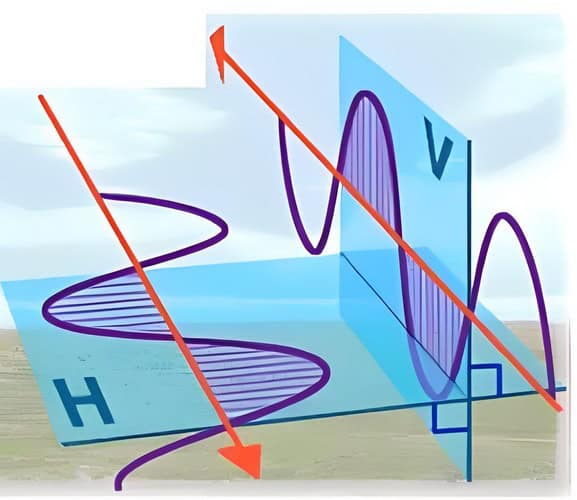
An OMT takes advantage of the orthogonality of electromagnetic wave polarizations. Electromagnetic waves can be polarized in different planes, such as horizontal and vertical, or left-hand and right-hand circular polarizations. An OMT is designed to handle two orthogonal polarizations, separating them into different paths or combining them into a single waveguide.
Structure
1. Waveguide Ports: An OMT typically has three or four ports:
cURL Too many subrequests.
cURL Too many subrequests.
cURL Too many subrequests.
cURL Too many subrequests.
cURL Too many subrequests.
cURL Too many subrequests.
cURL Too many subrequests.
cURL Too many subrequests.
cURL Too many subrequests.
cURL Too many subrequests.
Applications
cURL Too many subrequests.
cURL Too many subrequests.
cURL Too many subrequests.
Advantages
cURL Too many subrequests.
cURL Too many subrequests.
cURL Too many subrequests.
cURL Too many subrequests.
cURL Too many subrequests.
cURL Too many subrequests.
1. Polarization Isolation: OMTs are designed to separate orthogonal polarizations, allowing for efficient use of both horizontal and vertical polarizations. This isolation minimizes interference between signals that are polarized differently.
2. Increased Bandwidth: By utilizing both polarizations, OMTs effectively double the capacity of a communication channel, enabling higher data throughput without requiring additional spectrum.
3. Improved Signal Quality: The isolation provided by OMTs helps reduce cross-polarization interference, leading to clearer and more reliable signal transmission and reception.
4. Space Efficiency: OMTs allow for the use of a single antenna to handle multiple signals with different polarizations. This reduces the need for multiple antennas, saving physical space and reducing structural complexity.
5. Cost Efficiency: By enabling the use of a single antenna for multiple polarizations, OMTs can reduce the overall cost of the antenna system, including installation and maintenance costs.
6. Versatility: OMTs are versatile and can be used in various applications, including satellite communications, radar systems, and terrestrial microwave links. They are suitable for both transmitting and receiving systems.
7. Enhanced System Performance: In satellite communication systems, OMTs allow for better utilization of the available spectrum and improved link performance, which is critical for high-demand applications like broadband internet and high-definition television.
8. Compatibility: OMTs can be integrated with various types of waveguides and coaxial systems, making them compatible with a wide range of existing infrastructure and equipment.
Overall, orthomode transducers are valuable components in modern communication systems, enhancing performance, efficiency, and reliability.
What does the OMT consist of?
An Orthomode Transducer (OMT) is a specialized microwave waveguide component used primarily in antenna systems to separate or combine signals of different polarizations. It is commonly used in satellite communications and radar systems. The OMT typically consists of the following key components:
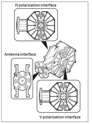
1. Waveguide Ports:
Common Port: This is the port where the combined signal (both polarizations) is either received or transmitted.
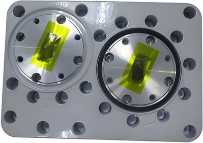
Horizontal Polarization Port: This port is designed to handle signals that are horizontally polarized.
Vertical Polarization Port: This port is designed to handle signals that are vertically polarized.
2. Waveguide Junction: This is the central part of the OMT where the waveguide branches into different paths. It is engineered to ensure that signals of different polarizations are directed to their respective ports with minimal loss and interference.
3. Mode Filters or Mode Converters: These components ensure that only the desired polarization mode passes through each path. They help in maintaining the purity of the polarization by filtering out unwanted modes.
4. Transition Sections: These sections provide smooth transitions between different waveguide sizes or shapes to ensure efficient signal transmission and minimal reflection.
5. Isolation Structures: These structures are designed to minimize the coupling between the horizontal and vertical polarization ports, ensuring that the signals remain isolated from each other.
6. Mechanical Housing: The entire assembly is housed in a robust mechanical structure to protect the internal components and ensure stable operation under various environmental conditions.
The design of an OMT can vary depending on the specific application and frequency range, but the core principle remains the same: to separate or combine orthogonal polarizations efficiently.
How to choose the right orthomode transducer (OMT)?
Choosing the right orthomode transducer (OMT) involves several key considerations to ensure it meets your specific application requirements. Here are the primary factors to consider:
cURL Too many subrequests.
Ensure the OMT supports the frequency range of your application. OMTs are designed for specific frequency bands, such as X-band, Ku-band, Ka-band, etc.
cURL Too many subrequests.
Determine the type of polarization you need. OMTs are used to separate or combine orthogonal polarizations (horizontal and vertical). Ensure the OMT can handle the polarization requirements of your system.
3. Insertion Loss:
Check the insertion loss specifications. Lower insertion loss is preferable as it means less signal loss when the signal passes through the OMT.
4. Isolation:
High isolation between ports is crucial to minimize interference between the orthogonal polarizations. Look for OMTs with high isolation values.
5. Return Loss (VSWR):
Good return loss (or Voltage Standing Wave Ratio, VSWR) is important for efficient signal transmission. Lower VSWR indicates better impedance matching and less signal reflection.
6. Power Handling:
Ensure the OMT can handle the power levels in your application. This is particularly important in high-power transmission systems.
7. Connector Types:
Verify the types of connectors used on the OMT and ensure they are compatible with your existing equipment. Common connector types include waveguide flanges, SMA, N-type, etc.
8. Mechanical Design:
Consider the physical dimensions and weight of the OMT to ensure it fits within your system’s spatial constraints. Also, consider the durability and environmental specifications if the OMT will be used in harsh conditions.
9. Temperature Range:
Ensure the OMT can operate within the temperature range of your application environment. This is particularly important for outdoor or space applications.
cURL Too many subrequests.
Choose OMTs from reputable manufacturers known for quality and reliability. Good technical support and warranty services can be crucial for troubleshooting and maintenance.
11. Cost:
cURL Too many subrequests.
cURL Too many subrequests.
cURL Too many subrequests.
cURL Too many subrequests.
cURL Too many subrequests.
cURL Too many subrequests.
cURL Too many subrequests.
cURL Too many subrequests.
cURL Too many subrequests.
cURL Too many subrequests.
cURL Too many subrequests.
cURL Too many subrequests.
cURL Too many subrequests.
cURL Too many subrequests.
cURL Too many subrequests.
cURL Too many subrequests.
cURL Too many subrequests.
cURL Too many subrequests.
cURL Too many subrequests.
Mode Coupling: Analyze the coupling between different modes using Maxwell’s equations.
Impedance Matching: Design impedance matching sections to minimize reflection.
Isolation Techniques: Implement techniques like septum polarizers, irises, or filters to achieve high isolation.
4. Detailed Design
CAD Modeling: Use CAD software (e.g., CST Microwave Studio, HFSS) to create a detailed 3D model of the OMT.
Simulation: Simulate the electromagnetic performance using software tools to analyze S-parameters, field distributions, and optimize the design.
Optimization: Iterate the design to optimize performance metrics such as insertion loss, isolation, and return loss.
5. Prototyping
Material Selection: Choose appropriate materials (e.g., aluminum, copper) considering conductivity, weight, and thermal properties.
Manufacturing: Fabricate the prototype using techniques like CNC machining, 3D printing, or electroforming.
Assembly: Assemble the components ensuring precise alignment and minimal gaps.
6. Testing and Validation
Measurement Setup: Set up a test bench with network analyzers, power meters, and other necessary equipment.
Performance Testing: Measure S-parameters (S11, S21, S31, etc.), insertion loss, isolation, and return loss across the operating frequency range.
Environmental Testing: Conduct thermal, vibration, and other environmental tests if required.
7. Iteration and Refinement
Analyze Results: Compare the measured performance with simulated results.
Identify Issues: Identify and troubleshoot any discrepancies or performance issues.
Refinement: Make necessary adjustments to the design and repeat the testing process.
8. Final Documentation
Technical Documentation: Prepare detailed documentation including design specifications, simulation results, manufacturing drawings, and test reports.
User Manual: Create a user manual for the operation and maintenance of the OMT.
9. Production
Scaling: If the design meets all specifications, proceed to scale up for production.
Quality Control: Implement quality control processes to ensure consistency and reliability in mass production.
Example Design Elements
Waveguide Sections: Design different sections of the waveguide to support and transition between modes.
Mode Filters: Implement filters to block unwanted modes.
Septum Polarizer: Use a septum polarizer to separate orthogonal polarizations.
T-Junctions and Y-Junctions: Employ junctions for splitting and combining signals.
Tools and Software
Electromagnetic Simulation: CST Microwave Studio, Ansys HFSS, COMSOL Multiphysics.
CAD Software: AutoCAD, SolidWorks, CATIA.
Measurement Equipment: Vector Network Analyzer (VNA), Spectrum Analyzer, cURL Too many subrequests.
cURL Too many subrequests.
cURL Too many subrequests.
cURL Too many subrequests.
cURL Too many subrequests.
cURL Too many subrequests.
cURL Too many subrequests.
cURL Too many subrequests.
cURL Too many subrequests.
cURL Too many subrequests.
cURL Too many subrequests.
cURL Too many subrequests.
cURL Too many subrequests.
cURL Too many subrequests.
cURL Too many subrequests.
cURL Too many subrequests.
cURL Too many subrequests.
cURL Too many subrequests.
cURL Too many subrequests.
5. Applications: Used in radar systems, satellite communications, microwave ovens, and various other RF and microwave systems.
Comparison
1. Function:
OMT: Primarily used to separate or combine orthogonal polarizations of signals.
Waveguide: Used to guide electromagnetic waves from one point to another.
2. Design:
OMT: More complex design to handle dual polarizations and ensure high isolation between channels.
Waveguide: Simpler in design, focusing on efficient wave propagation.
3. Applications:
OMT: Specialized applications requiring dual polarization, such as satellite communication.
Waveguide: Broad range of applications including signal transmission in radar, communication systems, and industrial heating.
4. Complexity:
OMT: More complex due to the need to handle and separate orthogonal polarizations.
Waveguide: Generally simpler, focusing on efficient and low-loss transmission of signals.
Conclusion
While both OMTs and waveguides are essential in RF and microwave engineering, they serve different roles. OMTs are specialized for handling and separating orthogonal polarizations, making them invaluable in applications like satellite communications where polarization diversity is crucial. Waveguides, on the other hand, are fundamental components for guiding electromagnetic waves with high efficiency and low loss across a wide range of applications. Understanding the specific requirements of your application will help determine which component is most suitable.
cURL Too many subrequests.
In conclusion, OMTs are an essential component in communication systems. They allow for the simultaneous transmission and reception of multiple signals using a single antenna. OMTs provide isolation between the transmit and receive paths, improve signal quality, and increase the overall efficiency of a communication system. Whether you’re working on a satellite communication system, radar system, or wireless communication network, understanding and utilizing OMTs effectively can greatly enhance the performance of your projects.