 Skip to content

In the intricate world of telecommunications, the functionality of an antenna is profoundly influenced by its feeding network. This pivotal component ensures that signals are efficiently transmitted and received, playing a crucial role in the antenna’s overall performance. But what exactly is an antenna feeding network, and why is it so critical?
An antenna feeding network comprises the complex assembly of cabling, connectors, and distribution mechanisms that facilitate the flow of signals between an antenna and its transmitter or receiver. By seamlessly matching the antenna’s impedance to that of the connected device, these networks are fundamental in maximizing efficiency and reducing signal degradation.
As we dive deeper into the essence of antenna feeding networks, we’ll uncover the specifics that render them indispensable in the realm of modern communications.
What is an antenna feedline?
Feedlines are typically made of coaxial cable, which consists of a center conductor surrounded by an insulating layer, a metal shield, and an outer jacket. The center conductor carries the RF signal, while the shield prevents interference and minimizes signal loss. The insulating layer separates the center conductor from the shield to prevent electrical contact and maintain the integrity of the signal.
Other types of feedlines include twin-lead, which consists of two parallel wires, and waveguides, which are hollow metal tubes that guide RF signals. Each type of feedline has its advantages and disadvantages, and the choice depends on factors such as frequency, power, and distance.
It is important to select the appropriate feedline for an antenna system to ensure efficient signal transfer and minimize losses. Factors such as the length of the feedline, the type of cable, and the presence of bends or kinks can all affect the performance of the antenna system.
What is a feed network?
The feed network is responsible for delivering the RF (Radio Frequency) signal to each element of the antenna array. It is designed to ensure that the signal is properly distributed to each element with the correct phase and amplitude. The feed network can be a simple system of transmission lines or a more complex network that includes phase shifters, power dividers, and other components. The design of the feed network is crucial to achieving the desired performance of the antenna system.
What are the radiation and loss characteristics of microstrip antennas with a corporate feed network?
When it comes to microstrip antennas employing a corporate feed network, understanding both radiation behavior and associated losses is essential for optimizing performance. In these systems, the interconnected feed lines are designed to distribute the RF signal evenly to each antenna element, but the configuration also introduces unique considerations.
Radiation Characteristics:
Corporate feed networks can impact the overall radiation pattern of the antenna array. Some radiation can occur directly from the feed lines themselves, not just the patches, especially at bends or discontinuities. This parasitic radiation can subtly alter the intended beam shape and reduce efficiency if not carefully managed.
Loss Mechanisms:
Losses in a microstrip corporate feed network arise from two main sources:
- Conductor and dielectric losses: The thin metal traces and dielectric materials used in microstrip fabrication inherently dissipate some energy as heat, particularly at higher frequencies.
- Surface waves and leakage: Energy can be lost into the substrate as surface waves, which reduces the amount of power radiated into free space.
Because of these factors, designers must balance layout complexity, trace width, and substrate selection. Using high-quality materials and thoughtful routing techniques (avoiding unnecessary bends and impedance mismatches) can help minimize both unintended radiation and energy losses.
With these aspects in mind, a well-designed corporate feed network enables precise control over signal distribution while mitigating efficiency losses—laying the groundwork for robust antenna performance.
Effects of Free-Space Radiation and Surface-Wave Excitation in Printed Feed Networks
When it comes to printed feed networks, two phenomena often come into play: free-space radiation and surface-wave excitation. Both can significantly influence the performance and efficiency of your antenna system.
Free-space radiation occurs when a portion of the signal unintentionally radiates away from the feed network, rather than being channeled to the intended antenna elements. This can lead to unwanted signal loss and potential interference with neighboring circuits or systems. For engineers working with high-frequency PCB-based antennas, this is a key concern because even minor radiation can degrade the integrity of your signal, especially in compact devices or densely populated boards.
Meanwhile, surface-wave excitation refers to the trapping and propagation of RF energy along the surface of the substrate material, rather than through the desired transmission paths. Surface waves can divert energy away from the intended antenna elements, introduce signal delays, and sometimes even couple into other components, causing unplanned interactions and reduced overall efficiency.
Both of these effects can lead to decreased antenna gain, unwanted noise, and diminished system reliability. Design strategies such as careful layout, the use of ground planes, and appropriate shielding are crucial to minimize their impact. Recognizing and addressing these potential pitfalls ensures that printed feed networks deliver robust, high-performance results in modern wireless applications.
How do gain and directivity change with large antenna arrays?
When it comes to large microstrip antenna arrays—think 16, 64, 256, or even 1024 individual elements—the gain and directivity tend to scale significantly with the number of elements used. As the size of the array increases, both gain and directivity improve, allowing for more focused signal transmission and reception.
- Gain: Larger arrays concentrate transmitted energy more effectively. For instance, moving from a 16-element to a 1024-element array, you will notice a marked increase in gain. This means the system can transmit signals over greater distances with less power loss.
- Directivity: Similarly, as the array grows, the antenna’s ability to focus its beam in a specific direction sharpens. A 1024-element array can target its signal far more narrowly compared to a 16-element counterpart, which is invaluable in high-frequency applications like 5G base stations or advanced radar systems.
- Frequency Range: These effects are more pronounced in higher frequency bands—such as those between 10 GHz and 35 GHz—where precise control and minimal interference are critical.
In short, scaling up the number of elements in an antenna array directly enhances both its gain and directivity, making large arrays an essential choice for applications where signal clarity and range are key considerations.
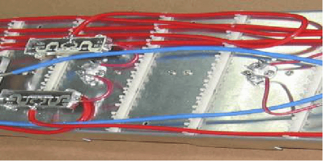
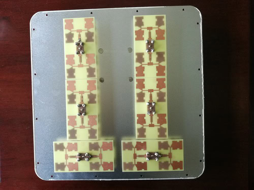
Performance of a Four-Element Microstrip Array Antenna
To assess the effectiveness of a four-element microstrip array antenna, engineers examine key metrics such as radiation patterns, directivity, and gain—both through simulation and hands-on measurements. When designed with a corporate feed network, these antennas can be carefully analyzed by modeling the electrical currents in the feed lines, treating them similarly to ideal transmission lines.
In practical terms, the predicted radiation patterns of a well-designed four-element array tend to closely match experimental results. This holds true for both the shape and direction of the main beam, offering confidence in the reliability of simulation tools and design models. The corporate feed ensures that the signal is evenly distributed, which helps reduce unwanted side lobes and improves overall consistency.
Directivity—a measure of how focused the radiation is in a particular direction—shows notable improvement with this configuration compared to individual elements. Similarly, the gain, which indicates how effectively the antenna converts input power into radio waves in a given direction, aligns closely between predicted and measured values. Minor discrepancies may arise due to unavoidable losses or surface-wave effects in the feed network, but these are typically well-understood and manageable.
In summary, a four-element microstrip array antenna with a printed corporate feed network demonstrates predictable and efficient performance. The alignment between theoretical predictions and actual measurements highlights the value of careful feed network design in achieving optimal radiation characteristics.
What is meant by feeding in an antenna?
Feeding in an antenna refers to the process of connecting the antenna to a transmitter or receiver. It involves providing the necessary electrical connection between the antenna and the electronic device to enable the transfer of signals. The feeding method may vary depending on the type of antenna and the application, but it typically involves connecting a transmission line, such as a coaxial cable, to the antenna.
What is the feeding port of an antenna?
The feeding port is typically a physical connector, such as a coaxial connector or a waveguide flange, that allows for the connection of the feedline to the antenna. It is usually located at the center or at one end of the antenna structure. The type of feeding port used depends on the type of antenna and the frequency range of operation.
What are the methods of feeding in antennas?
There are several methods of feeding in antennas, including:
1. Direct feeding: In this method, the antenna is directly connected to the transmission line or the source of the signal. This is the simplest and most common method of feeding antennas.
2. Microstrip feeding: In microstrip antennas, the feed line is attached to the radiating patch using a microstrip transmission line. This method is commonly used in printed circuit board (PCB) antennas.
3. Coaxial feeding: Coaxial feeding involves using a coaxial cable to connect the antenna to the source. The center conductor of the coaxial cable is connected to the antenna, while the outer conductor is connected to the ground.
4. Waveguide feeding: Waveguide feeding is used in high-frequency antennas. The antenna is connected to a waveguide, which guides the electromagnetic waves to the antenna.
5. Aperture coupling: In aperture-coupled feeding, the antenna is fed through an aperture in a metallic plate. The energy is coupled from the plate to the antenna through the aperture.
6. Proximity coupling: Proximity coupling involves placing the feed line close to the antenna without any direct connection. The electromagnetic field generated by the feed line couples with the antenna and transfers energy.
7. Horn feeding: Horn feeding is used in horn antennas, where the feed line is connected to the horn structure. The horn helps to guide and shape the electromagnetic waves.
8. Slot feeding: In slot antennas, the feed line is connected to a slot in a metallic plate. The electromagnetic waves are radiated through the slot.
These are just a few examples of the various methods of feeding in antennas. The choice of feeding method depends on the type of antenna, the frequency of operation, and the desired performance characteristics.
How can a surface current approach be used to model electrical currents in the feed lines of microstrip antennas?
A surface current approach is a useful method for analyzing how electrical currents flow in the feed lines of microstrip antennas, especially those with a corporate feed network. In this approach, the currents along the feed lines are approximated as if they behave like ideal transmission lines. By representing the current distribution as surface currents, engineers can more easily predict how energy travels through the feed network, where losses might occur, and how efficiently power is delivered to each patch or element of the antenna.
This method helps in evaluating both the radiation from the feed lines themselves, which can introduce unwanted losses, and the overall performance of the antenna array. It’s particularly helpful during the design phase, allowing for adjustments to the feed network layout to minimize losses and unwanted emissions. Using this technique ensures that designers can optimize the microstrip antenna system for their intended application, balancing efficiency and practical construction constraints.
When evaluating microstrip array antennas across a frequency range of 10 to 35 GHz, various configurations—such as arrays composed of 16, 64, 256, and even up to 1024 elements—have been analyzed for their gain and directivity. Both calculations and practical measurements show that as the number of elements in the array increases, the overall gain and directivity of the antenna system also improve significantly. For example, a 1024-element array will typically demonstrate much sharper beam steering and higher gain compared to smaller arrays, making it highly effective for applications in satellite communications and radar systems.
Laboratory measurements of these arrays indicate consistent results with theoretical predictions, with performance metrics showing reliable operation throughout the specified frequency band. Advances in fabrication techniques and materials—such as those used in PCB-based microwave antennas from manufacturers like Rogers Corporation or Taconic—help to maintain low losses and precise element spacing even at higher frequencies.
Overall, the performance of microstrip array antennas in this frequency range demonstrates strong alignment between calculated and measured values, yielding high efficiency and directionality suitable for demanding wireless applications.
What is a coaxial feed line?
The central conductor of a coaxial feed line carries the signal, while the outer conductor acts as a shield to prevent interference from external sources. The insulating spacer between the two conductors maintains a constant distance and prevents them from coming into contact with each other. The protective outer sheath provides mechanical strength and insulation.
Coaxial feed lines are used in various applications, including telecommunications, cable television, computer networks, and radio frequency (RF) systems. They can transmit both analog and digital signals, making them versatile for different types of data transmission. Coaxial cables come in various sizes and specifications, depending on the specific application and signal requirements.
What is coaxial feed in an antenna?
The coaxial feed consists of a coaxial cable that carries the radio frequency (RF) signal from the transmitter or receiver to the antenna. The center conductor of the coaxial cable is connected to the antenna, while the outer conductor serves as a shield to protect the signal from external interference. This type of feed is commonly used in various types of antennas, including dipole antennas, yagi antennas, and parabolic antennas.
How do you use a feeding port?
To use a feeding port, follow these steps:
1. Ensure that the antenna is properly installed and positioned for optimal reception or transmission.
2. Connect the feedline, which is typically a coaxial cable, to the feeding port on the antenna. The feedline should have a connector that matches the type of feeding port on the antenna.
3. Insert the connector into the feeding port until it is fully seated.
4. Tighten any locking mechanisms or screws on the feeding port to secure the connection. This will prevent the connector from coming loose or disconnecting during use.
5. Check the connection to ensure that it is tight and secure. Wiggle the connector gently to make sure it does not move or come loose.
6. Inspect the connection for any visible damage or signs of wear. If there are any issues with the connector or the feeding port, replace them before use.
7. Verify that there are no impedance mismatches between the feedline and the feeding port. Mismatches can cause signal loss or reflections, reducing the antenna’s performance.
8. Test the antenna to ensure that it is functioning properly. Check for any signal degradation, weak reception, or poor transmission quality.
9. If necessary, make adjustments to the antenna’s position or orientation to optimize its performance.
10. Regularly inspect and maintain the feeding port and the connector to prevent any damage or degradation over time.
In summary, antenna feeding networks are essential for connecting antennas to the devices they communicate with. By improving and optimizing these networks, the telecommunications industry can progress further, leading us to a future where connectivity is effortless and available to everyone. Let us accept the challenges and prospects in this crucial field, pushing the limits of what wireless communication can achieve.