 Skip to content
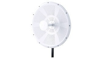
A parabolic dish antenna is an antenna that uses a parabolic reflector to direct radio waves into a single focal point. This focusing of the radio waves increases the antenna’s gain or the signal’s power.
A typical parabolic dish antenna consists of two main parts:
- The parabolic dish reflector: This is the large, curved surface that “collects” incoming radio waves or focuses outgoing waves.
- The feed antenna: Positioned at the focal point of the dish, this component transmits or receives the signal that the dish reflects.
The highly directional nature of a parabolic dish antenna allows it to both transmit and receive signals with high gain and a narrow beam width, making it ideal for long-distance, point-to-point communication.
The size and shape of a parabolic dish antenna’s reflector determine its gain. More giant reflectors produce more gain than smaller reflectors, and the shape of the reflector also affects the antenna’s gain. For instance, a parabolic dish antenna with a circular reflector has more gain than an antenna with a square reflector.
The gain of a parabolic dish antenna can be increased even further by using a feedhorn. A feedhorn is a cone-shaped device that directs the radio waves into the reflector. The feed horn helps to focus the energy of the radio waves, which increases the antenna’s gain.
Parabolic dish antennas are often used in Point-to-Point communications systems. The high gain of these antennas allows them to receive signals from other backhauls such as base stations or repeaters. For WLAN/WiFi dish antenna, the gain ranges from 18dBi to 40dBi between 2.4GHz and 6.5GHz, depending on the exact frequency range and reflector diameter.
How Do You Measure the Gain of Parabolic Dish Antenna?
The gain of a parabolic dish antenna can be measured by calculating its signal-to-noise ratio (SNR). The SNR measures the signal’s power compared to the noise’s power. The higher the SNR, the greater the gain of the antenna.
Some factors that can affect the SNR of a parabolic dish antenna include the size and shape of the reflector, the type of feed horn used, and the distance between the antenna and the reflector. The type of material used to make the reflector can also affect the gain of a parabolic dish antenna. Aluminum is a common material for making parabolic dish antennas because it has a high reflectivity or the ability to reflect radio waves.
Calculating Gain with Physical Parameters
In addition to measuring SNR, the gain of a parabolic reflector antenna can also be estimated using its physical characteristics. The main parameters required are:
- Diameter of the reflector: Larger diameters generally yield higher gain.
- Operating frequency: Higher frequencies (shorter wavelengths) can increase gain for a given reflector size.
The gain (in decibels, dBi) can be calculated using the following formula:
</span> <span style=”color: #0C882A;”>Gain (dBi) = 10 * log10 [ (η * (π * D / λ)^2) ]</span> <span style=”color: #0C882A;”>
Where:
- η is the efficiency of the antenna (typically between 0.5 and 0.7 for practical dishes)
- D is the diameter of the reflector
- λ is the wavelength of the signal (λ = speed of light / frequency)
For example, if you have a 1-meter diameter aluminum parabolic dish operating at 2.4 GHz (λ ≈ 0.125 meters) with an efficiency of 0.6, you can plug these values into the formula to estimate the theoretical maximum gain.
Practical Considerations
While calculations provide a useful estimate, real-world measurements may vary due to imperfections in the dish shape, feed alignment, or obstructions. Therefore, both calculation and direct measurement (such as SNR testing or using an antenna test chamber) are important when determining the actual gain of a parabolic dish antenna.
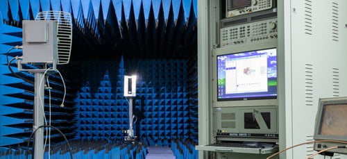
At Sanny Telecom, the gain of the WiFi parabolic dish antenna is tested by an antenna testing system in the antenna chamber. The test system includes both hardware and software. The major hardware consists of an antenna chamber, automatic rotation table, transmitter, receiver, and standard gain horn antenna.
Formula for Calculating Parabolic Dish Antenna Gain
To determine the gain of a parabolic dish antenna, you can use a well-established mathematical formula. The most common equation is:
Gain (G) = (π × D / λ)² × η
Where:
- D is the diameter of the parabolic dish
- λ (lambda) is the wavelength of the signal
- η (eta) represents the efficiency of the antenna, typically ranging from 0.5 to 0.7 for most practical designs
This formula highlights how a larger dish diameter and shorter wavelength both contribute to higher gain. For WiFi and other high-frequency bands, even modest increases in dish size can make a significant difference in performance.
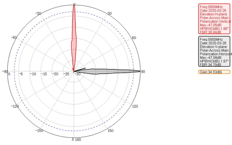
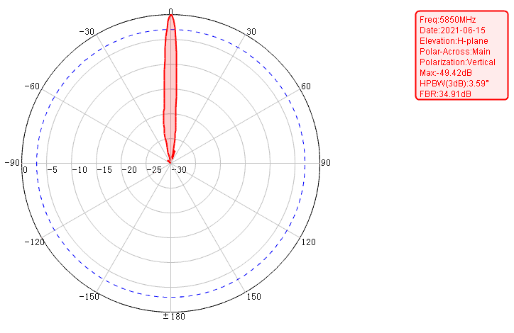
Parabolic Dish Antenna Radiation Pattern
The radiation pattern of a parabolic dish antenna is a graph that shows the direction of the radio waves emitted by the antenna. This pattern can determine the antenna’s gain in different directions.
The radiation pattern of a parabolic dish antenna is usually symmetrical, meaning that it is the same in both directions. This symmetry allows the antenna to emit radio waves in all directions equally. The radiation pattern of a parabolic dish antenna also has a lobe in the focal point’s direction, and the antenna’s gain is highest in this direction.
The radiation pattern of a parabolic dish antenna can determine the best location for the antenna. The antenna should be positioned so that the lobe in the radiation pattern is pointing in the desired direction.
What is the Beamwidth of a Parabolic Dish Antenna?
The beamwidth of a parabolic dish antenna is the angle between the two directions where the antenna’s gain is half its maximum value. This angle is typically measured in degrees.
The beamwidth of a parabolic dish antenna is determined by the size and shape of the reflector. Larger reflectors have a narrower beamwidth than smaller reflectors, and the shape of the reflector also affects the antenna’s beamwidth. For example, a parabolic dish antenna with a circular reflector has a narrower beamwidth than an antenna with a square reflector.
The beamwidth of a parabolic dish antenna can be used to determine the size of the antenna. The antenna should be sized so that the beamwidth is large enough to cover the desired area.
How is BeamWidth Related to Antenna Gain?
The beamwidth of a parabolic dish antenna is inversely proportional to the antenna’s gain. It means that as the beamwidth of the antenna increases, the gain of the antenna decreases.
This relationship is because a parabolic dish antenna has a narrow beamwidth in the direction of its maximum gain. As the beamwidth of the antenna increases, the amount of energy it emits in this direction decreases, and this decreases the antenna’s gain.
The beamwidth of a parabolic dish antenna can be used to determine the antenna’s gain. The antenna should be sized so that the beamwidth is large enough to cover the desired area.
WiFi Parabolic Dish Antenna Diameter (Meters/Feet)
The diameter of a parabolic dish antenna is the size of the reflector in meters or feet, and this size affects the antenna’s gain.
A bigger diameter reflector results in a higher gain antenna, and this is because a larger reflector has more surface area than a smaller reflector. This increased surface area allows the antenna to emit radio waves in all directions equally.
A larger diameter reflector also results in a narrower beamwidth, and this is because a larger reflector has less curvature than a smaller reflector. The beamwidth of an antenna is inversely proportional to its gain, so a larger diameter reflector results in a narrower beamwidth.
The optional diameter of a WiFi parabolic solid dish antenna can be: 0.36m, 0.4m, 0.6m, 0.9m, 1.2m,1.5m, 1.8m
| Dish antenna diameter (meter) | Dish antenna diameter (feet) |
| 0.36 | 1.18 |
| 0.4 | 1.31 |
| 0.6 | 2.0 |
| 0.9 | 3.0 |
| 1.2 | 4.0 |
| 1.8 | 6.0 |
WiFi Parabolic Dish Antenna Frequency Range & Applications
The frequency range and applications of a parabolic dish antenna are determined by the size and shape of the reflector.
A WiFi parabolic dish antenna with a circular reflector is typically used for frequencies between 2.4GHz and 6.4 GHz.
A parabolic dish antenna has diverse applications, including Point-to-Point wireless communication, Wireless Bridges and Backhaul, Closed Circuit Television(CCTV), etc.
The most common WiFi Parabolic dish antenna is the 5.8GHz dual-polarization 30dBi and 34dBi versions. They are widely used for outdoor LOS (Light of Sight)applications worldwide.
WiFi Parabolic Dish Antenna Gain vs. Diameter
The gain mainly depends on the operating frequency and the reflector’s diameter. The higher the frequency, the higher the gain. A higher frequency means a shorter wavelength—a shorter wavelength results in a narrower beamwidth, and a narrower beamwidth means a higher gain antenna. It means a better signal quality and a more extended range. The antenna gain is usually specified at the center frequency of the antenna.
The diameter of the reflector has the most impact on the antenna gain. A larger reflector diameter results in a higher antenna gain, and a larger reflector has more surface area than a smaller reflector. This increased surface area allows the antenna to emit radio waves in all directions.
A larger diameter reflector also results in a narrower beamwidth, and this is because a larger reflector has less curvature than a smaller reflector. The beamwidth of an antenna is inversely proportional to its gain, so a larger diameter reflector results in a narrower beamwidth.
How Parabolic Reflector Gain is Determined
A parabolic reflector antenna is highly directional, transmitting or receiving signals with high gain and a small beamwidth. This is achieved thanks to its two main parts: a parabolic dish reflector and a feed antenna located at the focal point of the dish. The parabolic shape focuses incoming or outgoing signals, enhancing directivity and increasing propagation distance.
The gain of a parabolic dish antenna can be estimated using the following formula:
Gain (linear) = Efficiency × (π × D / λ)²
Gain (dBi) = 10 × log₁₀ [Efficiency × (π × D / λ)²]
Where:
- D = diameter of the parabolic reflector dish
- λ (lambda) = wavelength corresponding to the operating frequency
- Efficiency typically ranges from 0.5 to 0.7 for practical antennas
Because the calculation can be time-consuming, especially for complex designs or when optimizing for specific frequencies, engineers often use gain calculators for quick results. These calculators require the dish diameter and the operating frequency as inputs, then provide the expected gain and wavelength.
In summary, both the operating frequency and the diameter of a parabolic dish play crucial roles in determining antenna gain. Higher frequencies (shorter wavelengths) and larger diameters both contribute to greater gain and narrower beamwidth, which translates to better signal quality and longer range—key reasons why these antennas are favored for point-to-point wireless links and other long-distance applications.
WiFi 2.4-2.5GHz Parabolic Dish Antenna vs. Diameter
| Parabolic Reflector Diameter | Parabolic Solid Dish Antenna Gain |
| Φ0.4m | 20dBi |
| Φ0.6m | 24dBi |
| Φ0.9m | 27dBi |
WiFi 4.9-6.5GHz Parabolic Dish Antenna vs. Diameter