 Skip to content

Designing an RFID (Radio-Frequency Identification) antenna involves several critical steps to ensure the antenna meets the required specifications and performs effectively in its intended application. Here’s a step-by-step guide based on the principles outlined:
Define the application requirements
Once you have a clear understanding of the requirements, you can begin researching and evaluating different RFID systems that meet those requirements. Look for systems that operate within the desired frequency range and offer the required read range.
Consider the type of tags that are compatible with the system. Some systems may only work with specific tag types, such as passive or active tags. Make sure the tags you plan to use are supported by the system.
Evaluate the system’s read range capabilities. This is the maximum distance at which the system can read tags. If you need to read tags from a long distance, such as several meters away, make sure the system can meet that requirement.
Consider the orientation of the tags. Some systems may require the tags to be in a specific orientation to be read properly. For example, some systems may require tags to be aligned horizontally, while others can read tags in any orientation. Make sure the system can read tags in the desired orientation.
Consider other features and capabilities of the system that may be important to your specific use case. This could include things like data storage capabilities, integration with other systems, or the ability to read multiple tags simultaneously.
Once you have evaluated different RFID systems based on these criteria, you can select the system that best meets your requirements.
Determine the antenna type
The appropriate type of RFID antenna depends on the application requirements and the available space for installation. Here are some guidelines for selecting the appropriate type:
1. Dipole Antenna: This is the most common type of RFID antenna and is suitable for most applications. It is a simple, straight antenna that radiates in a doughnut-shaped pattern. Dipole antennas are omnidirectional, meaning they radiate in all directions, making them ideal for applications where the tag can be in any orientation.
2. Linear Polarized Antenna: This type of antenna radiates in a straight line, either horizontally or vertically. Linear polarized antennas are useful in applications where the tag is always in the same orientation, such as conveyor belt systems or gate readers.
3. Circular Polarized Antenna: This type of antenna radiates in a circular pattern, allowing for greater flexibility in tag orientation. Circular polarized antennas are ideal for applications where the tag can be in different orientations or where the tag is moving.
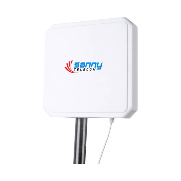
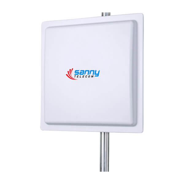
4. Patch Antenna: This type of antenna is flat and compact, making it suitable for applications with limited space. Patch antennas are directional and have a narrow beam width, making them ideal for applications where the tag is always in the same location and direction.
5. Near Field Antenna: This type of antenna is used for short-range applications, typically within a few centimeters. Near field antennas are ideal for applications where the tag needs to be very close to the reader, such as access control systems or keyless entry systems.
In summary, when selecting the appropriate type of RFID antenna, consider the application requirements,read range, directionality, available space, the proximity of the tag to the antenna, and the frequency of the RFID system.
Addressing Readability Issues at Different Tag Angles
You may notice that RFID tags can sometimes appear to “disappear” or become unreadable when they are positioned at certain angles to the antenna. This usually happens due to polarization mismatch between the antenna and the tag. In simple terms, if the tag’s orientation doesn’t align with the antenna’s electromagnetic field, the signal isn’t picked up effectively, resulting in missed reads.
To overcome this, consider using circularly polarized antennas. These antennas emit electromagnetic fields in a rotating pattern, allowing them to read tags regardless of their rotation or tilt. If you’re unsure which orientation your tags will be in during use, it’s a good practice to test tag readability at multiple angles before finalizing your antenna selection. This ensures consistent performance across real-world scenarios, whether your tags are fixed in place or moving around unpredictably.
Choose the substrate material
The choice of substrate material for an antenna can have a significant impact on its overall performance. There are several common options available, including FR-4, ceramic, and flexible materials, each with its own set of advantages and disadvantages. When selecting a substrate material, it is important to consider factors such as cost, durability, and the environmental conditions in which the antenna will be used.

1. Cost: The cost of the substrate material is an important consideration, especially for mass-produced antennas. FR-4 is generally the most cost-effective option, making it a popular choice for many applications. Ceramic substrates tend to be more expensive, while flexible materials can vary in cost depending on the specific material used.
2. Durability: The durability of the substrate material is crucial, particularly for outdoor or harsh environment applications. FR-4 is relatively durable and can withstand moderate mechanical stress and temperature variations. Ceramic substrates are highly durable and can handle extreme temperatures, making them suitable for high-power applications. Flexible materials are generally less durable and can be prone to damage if not handled carefully.
3. Environmental Conditions: The environmental conditions in which the antenna will be used should also be taken into account. FR-4 is suitable for most indoor applications and moderate outdoor conditions. However, it may not be the best choice for high humidity or high-temperature environments. Ceramic substrates are excellent for high-power and high-temperature applications, as they can handle extreme conditions. Flexible materials are often used in applications that require conformal or bendable antennas, such as wearable devices, but they may not be suitable for all environmental conditions.
4. Electrical Performance: Different substrate materials can have an impact on the electrical performance of the antenna. FR-4 has relatively low dielectric constant and loss tangent, which can affect the bandwidth and efficiency of the antenna. Ceramic substrates typically have higher dielectric constants and lower loss tangents, which can improve the performance of the antenna. Flexible materials can have variable electrical properties depending on the specific material used.
In summary, the choice of substrate material for an antenna should be based on a careful consideration of factors such as cost, durability, environmental conditions, and electrical performance requirements. Each substrate material has its own advantages and disadvantages, and selecting the most appropriate one will ensure optimal antenna performance in the desired application.
Calculate the dimensions
To calculate the dimensions of an antenna, you can use the formula or software tools. Here is a general process to calculate the dimensions of a dipole antenna:
1. Determine the desired frequency (f) for your antenna.
2. Calculate the wavelength (λ) using the formula: λ = c / f, where c is the speed of light (approximately 3 x 10^8 meters per second).
3. Divide the wavelength by 2 to find the length of each element of the dipole antenna (L): L = λ / 2.
4. Determine the diameter or thickness of the antenna elements based on the type of antenna you are using.
5. Ensure the dimensions of the antenna meet the requirements of your application, such as the size constraints, gain, and impedance matching.
Alternatively, you can use software tools such as antenna simulation software or online calculators that provide the dimensions of various antenna types based on the desired frequency and other parameters. These tools can help you optimize the antenna design for your specific application.
Design the antenna layout
A layout for an antenna on a chosen substrate material typically includes the following components:
1. Conductive Traces: These are the metallic elements that form the structure of the antenna. The shape and size of the traces depend on the type of antenna you are designing. For example, a simple dipole antenna may consist of two parallel conductive traces, while a patch antenna may have a rectangular or circular conductive trace.
2. Feeding Point: This is the location where the electrical signal is applied to the antenna. The feeding point is typically connected to a transmission line that carries the signal to the antenna. The position of the feeding point depends on the type of antenna and the desired radiation pattern.
3. Baluns or Matching Networks (if necessary): Baluns (balanced-to-unbalanced transformers) or matching networks may be required to ensure proper impedance matching between the antenna and the transmission line. These components help improve the efficiency and performance of the antenna.
To create a visual layout of the antenna on a chosen substrate material, you can use various software tools like computer-aided design (CAD) software, electromagnetic simulation software, or even drawing software like Adobe Illustrator or Microsoft Visio. These tools allow you to draw the conductive traces, feeding point, and any additional components necessary for your antenna design.
Fabricate the antenna
To transfer the antenna design onto the substrate material, follow these steps using a suitable fabrication method such as etching, printing, or other manufacturing techniques:
1. Prepare the substrate material: Clean the substrate material thoroughly to remove any dirt, dust, or contaminants. This ensures proper adhesion of the antenna design and improves the overall performance.
2. Prepare the design: Convert the antenna design into a suitable format for fabrication. This may involve converting it into a digital file (e.g., Gerber file) or preparing it for printing.
3. Etching: If you choose to use etching, follow these steps:
a. Apply a layer of resist material (e.g., photoresist) onto the substrate material.
b. Expose the resist material to light through a mask or template that contains the antenna design.
c. Develop the resist material to remove the unexposed areas, leaving only the pattern of the antenna design.
d. Etch the substrate material using a suitable etchant, such as a chemical solution or plasma, to remove the exposed areas and create the antenna pattern.
4. Printing: If you choose to use printing, follow these steps:
a. Use a suitable printing technique such as screen printing, inkjet printing, or flexographic printing.
b. Prepare a mask or template that contains the antenna design.
c. Apply conductive ink or paste onto the substrate material through the mask or template to create the antenna pattern.
d. Cure or dry the conductive ink or paste according to the manufacturer’s instructions.
5. Other manufacturing techniques: Depending on the chosen technique, follow the specific instructions for that method. For example, if you are using additive manufacturing (e.g., 3D printing), ensure that the printer settings are appropriate for the desired accuracy and precision.
6. Ensure accuracy and precision: During the fabrication process, pay attention to accuracy and precision. Use high-resolution masks or templates, precise printing techniques, or accurate etching parameters to achieve the desired antenna design. Periodically check the dimensions and features of the fabricated antenna to ensure it matches the original design.
By following these steps and ensuring accuracy and precision, you can successfully transfer the antenna design onto the substrate material using a suitable fabrication method.
Test the antenna
To test the performance of the fabricated antenna, follow these steps:
1. Connect the RFID reader to a computer or a power source.
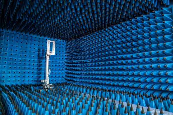
2. Place the fabricated antenna in a suitable location, such as an open area or a test chamber.
3. Power on the RFID reader and ensure it is in the correct mode for testing (e.g., read mode).
4. Set up a test scenario by placing an RFID tag at a specific distance from the antenna. This distance can be adjusted to measure the antenna’s read range.
5. Move the RFID tag closer or farther away from the antenna until the reader can no longer detect the tag. This distance is the read range of the antenna.
6. Note the read range and compare it to the desired read range specified in the antenna design.
7. Use a gain measurement device, such as a gain horn antenna or a gain measurement chamber, to measure the gain of the fabricated antenna. Follow the manufacturer’s instructions for the specific device being used.

8. Compare the measured gain to the desired gain specified in the antenna design.
9. Use a radiation pattern measurement device, such as a test chamber or a robotic arm with a probe antenna, to measure the radiation pattern of the fabricated antenna. Follow the manufacturer’s instructions for the specific device being used.
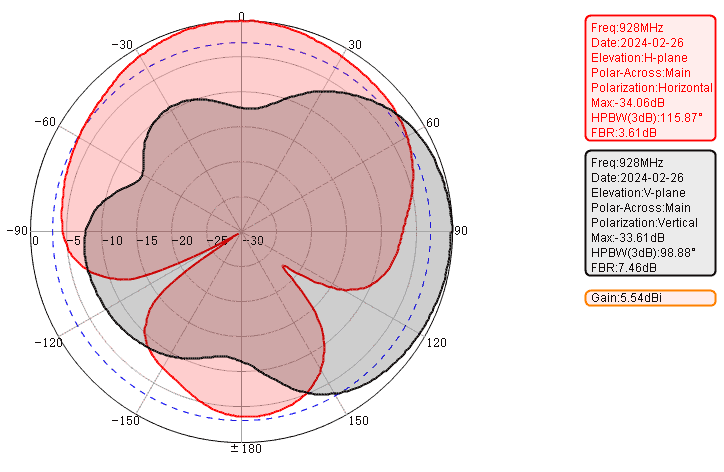
10. Compare the measured radiation pattern to the desired radiation pattern specified in the antenna design.
11. Analyze the test results and compare them to the desired performance specifications.
12. If the read range, gain, or radiation pattern do not meet the desired specifications, make necessary adjustments or optimizations to the antenna design.
13. Repeat the testing process after making adjustments to ensure the desired performance is achieved.
14. Document the final test results, including the read range, gain, and radiation pattern, for future reference and to verify the performance of the fabricated antenna.
Balancing Gain and Beamwidth for Optimal RFID Tag Coverage
When aiming for optimal RFID tag coverage, it’s important to find the right balance between antenna gain and beamwidth. A high-gain antenna can extend your read range, but it often results in a narrower beam. This means you’ll achieve excellent detection at longer distances, but may struggle to read tags that are close or positioned to the sides of the antenna.
To address this trade-off, consider the following strategies:
- Evaluate your coverage needs: If you need to detect tags spread across a wide area, opt for an antenna with a broader beamwidth—even if that means slightly lower gain.
- Combine multiple antennas: For environments where both long-distance and near-field detection are required, using several antennas with overlapping coverage can help eliminate dead zones.
- Experiment with placement and orientation: Adjusting the angle or height of the antenna can help shape the coverage to better suit your application.
- Use coverage maps: Tools from test equipment manufacturers like Keysight or Rohde & Schwarz can help you visualize the effective read zone of your setup, aiding in fine-tuning.
By thoughtfully combining these approaches, you can achieve a balance between gain and beamwidth, ensuring reliable detection both at a distance and close to the antenna.
Optimize the antenna
Once adjustments are made to the antenna design, it is necessary to repeat the testing process to determine if the desired performance specifications have been met. This involves following the same steps as before, including setting up the test environment, connecting the antenna to the appropriate equipment, and conducting the tests.
If the antenna meets the desired performance specifications, the design process is complete. However, if the antenna still does not meet the required criteria, further adjustments need to be made. This can include changing the dimensions of the antenna, modifying the layout, or adding additional components such as matching networks or baluns.
After making additional adjustments, the testing process needs to be repeated once again to determine if the changes have resulted in the desired performance improvements. This iterative process of adjusting the design and testing it continues until the antenna meets the required performance criteria.
Watch Out for Common Pitfalls
While optimizing and retesting, it’s easy to run into recurring issues. Here are a few frequently encountered problems, their likely causes, and straightforward fixes:
| Problem | Likely Cause | Fix |
| Simulation looks great but real-world performance is poor | Overlooking effects of nearby metal or liquid, incorrect material assumptions, poor soldering or feed connections | Build physical mock-ups, test in the actual environment, use absorbers or spacers as needed |
| Antenna matching shifts after production | PCB manufacturing tolerances, copper thickness, ambient humidity or temperature changes | Factor in tolerances, include tuning options like trim lines or small capacitors for field adjustment |
| Tags “disappear” at certain angles | Polarization mismatch between antenna and tag | Use circularly polarized antennas, or test with tags in multiple orientations |
| High gain antenna, but poor coverage near the reader | Beam is too narrow, missing nearby or off-axis tags | Balance gain and beamwidth, or employ multiple antennas to cover more area |
It is important to note that antenna design and optimization can be a complex and time-consuming process. It requires a good understanding of antenna theory, electromagnetic principles, and measurement techniques. Additionally, it often involves using specialized simulation software and equipment. Therefore, it is recommended to consult with experts or use professional services if you are not familiar with antenna design and optimization.
Enhancing RFID Antenna Performance: Multi-layer Structures, Smarter Matching, and Miniaturization
In the pursuit of higher performance, several advanced design strategies can be adopted to take RFID antennas to the next level.
Multi-layer Structures
Incorporating multi-layer elements—such as stacked rings, periodic slots, or folded traces—expands the antenna’s bandwidth and helps maintain consistent polarization characteristics. This layered approach allows for greater design flexibility. For example, engineers at organizations like Fraunhofer and Stanford have published research demonstrating that these structures can support stable operation even in challenging RF environments, where single-layer designs might falter.
Smarter Matching Techniques
Traditional antennas often use basic conjugate matching, but with RFID, there’s room to be cleverer. Optimizing the matching network not just for maximum received power, but also for improved backscatter (critical for RFID communication), increases overall system efficiency. Matching networks from brands like Mini-Circuits and offerings from Anritsu illustrate these high-performance approaches that ensure both reliable tag reading and strong backscatter signals—even as environmental or load conditions shift.
Miniaturization
Space is always at a premium, especially for embedded or wearable solutions. Using meandered traces and precision slot patterns, designers can shrink the antenna footprint substantially without sacrificing key parameters like gain or efficiency. These compact designs, reminiscent of those published in IEEE studies using fractal or serpentine layouts, are especially valuable when you need the antenna to disappear into the product chassis without a performance penalty.
By integrating these advanced strategies, RFID antenna designs can achieve improved bandwidth, stable signal performance, and more compact form factors, making them well-suited for real-world deployment in everything from industrial logistics to consumer electronics.
Integrate the antenna
Some considerations when integrating an antenna into a final product or system include:
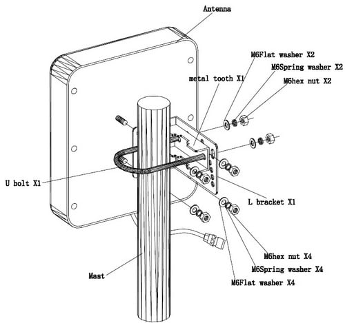
1. Mounting: Determine the best method for physically attaching the antenna to the product or system. This may involve using screws, brackets, adhesive, or other mounting hardware. Consider the size and weight of the antenna, as well as any space limitations, when choosing a mounting method.
2. Grounding: Antennas often require a ground plane to function properly. A ground plane is a conductive surface that helps to reflect the radio waves and improve the antenna’s performance. If the product or system does not have a built-in ground plane, you may need to add one. This could involve attaching a metal plate or wire mesh to the product or system, or using a ground plane kit specifically designed for the antenna.
Additional Grounding Considerations
When planning grounding for your antenna, keep the following practical details in mind:
- Material Selection: The choice of material for your ground plane matters. Metals like copper or aluminum are commonly used due to their excellent conductivity, but even a wire mesh can work in space-constrained designs.
- Size and Placement: The ground plane’s size should be proportional to the antenna’s wavelength and geometry. Too small, and you risk degraded performance; too large, and you might introduce unwanted effects in compact devices.
- Surface Effects: If your antenna will be mounted on or near metal, be aware that metal surfaces can drastically affect antenna impedance and radiation pattern. Testing with mock-ups or using absorber materials and clever spacing tricks can help overcome these challenges, particularly for UHF RFID applications.
- Environmental Interference: The presence of nearby objects—especially metal frameworks, liquids, or even glass—may require modifying your grounding approach. Real-world testing is essential, as simulation alone often misses these nuances.
Grounding isn’t just a box to check; it plays a vital role in ensuring optimal signal reflection, minimizing energy loss, and maximizing both read range and reliability. Proper attention to grounding can make the difference between a design that works on paper and one that performs consistently in the field.
3. Connectivity: Determine how the antenna will connect to the product or system. This may involve attaching a coaxial cable to the antenna and routing it to the appropriate connector on the product or system. Consider the length and type of cable needed, as well as any connectors or adapters that may be required.
4. Environmental considerations: Consider the environment in which the product or system will be used, and how this may affect the antenna. For example, if the product or system will be used outdoors, the antenna may need to be weatherproofed or protected from the elements. If the product or system will be used in a high-temperature environment, the antenna may need to be designed to withstand these temperatures.
It’s also essential to account for less-obvious environmental factors that can impact real-world antenna performance. Mounting an antenna near metal surfaces, on liquid containers, or inside enclosures can significantly alter its behavior compared to ideal lab conditions. For instance, a design that works flawlessly in simulation or on a test bench may see its range reduced dramatically when installed on a metal rack or near other electronic components. Effects such as reflections, absorption, and detuning can all occur due to proximity to different materials or environmental changes like humidity and temperature shifts.
Common issues and practical tips include:
- Material effects: Metal surfaces may reflect or detune the antenna signal, while liquids can absorb RF energy. Always test the antenna in the actual environment—mock-ups or prototypes are invaluable for revealing these real-world effects.
- Manufacturing tolerances: Variations in PCB copper thickness, soldering, or assembly can shift the antenna’s matching. When possible, allow for tuning adjustments (such as trimming lines or adding small capacitors) during integration.
- Environmental testing: Beyond temperature and weatherproofing, consider how mounting orientation, enclosure materials, and even nearby cabling can affect performance. Small adjustments, absorber materials, or repositioning may be required to maintain desired read range and efficiency.
Factoring in these considerations early in the design and integration process will help ensure your antenna performs reliably—not just in theory, but out in the field where it matters most.
5. Testing and validation: Once the antenna is integrated into the product or system, it is important to test and validate its performance. This may involve using a network analyzer or other test equipment to measure the antenna’s impedance, return loss, and radiation pattern. It may also involve testing the antenna in its intended application to ensure it meets the desired performance specifications.
6. Compliance: Ensure that the integrated antenna complies with applicable regulations and standards. Depending on the application and location, there may be specific requirements for electromagnetic compatibility (EMC), radio frequency (RF) exposure, or other regulatory requirements that the antenna must meet. Perform the necessary tests and obtain the appropriate certifications to ensure compliance.
7. Documentation: Document the integration process, including any modifications or adjustments made to the antenna design. This documentation will be useful for future reference and may be required for regulatory compliance or quality assurance purposes.
8. Production considerations: Consider the production process and any requirements or constraints that may impact the integration of the antenna. For example, if the product or system will be mass-produced, consider the cost, availability, and lead time of the antenna components. Also, consider any manufacturing or assembly steps that may be required to integrate the antenna into the product or system.
By considering these factors and following best practices, you can successfully integrate an antenna into a final product or system.
Conduct real-world testing
Once the RFID system with the integrated antenna has been developed, it is crucial to conduct real-world testing to validate its performance in different environments and scenarios. This testing will help identify any issues or areas for improvement that may not have been apparent during the development phase. Here are the steps involved in the real-world testing of the RFID system with the integrated antenna:
1. Define testing scenarios: Determine the different environments and scenarios in which the RFID system will be tested. This can include indoor and outdoor environments, different temperatures, varying levels of interference, and different tag placements.
2. Prepare test equipment: Set up the RFID system with the integrated antenna in each testing scenario. Ensure that the system is properly calibrated and ready for testing. Prepare a sufficient number of RFID tags to be used during the testing.
3. Conduct initial testing: Begin testing the RFID system in each scenario. Observe the system’s performance, including its read range, read accuracy, and response time. Note any unexpected behavior or issues that arise during the testing.
4. Analyze test results: Collect and analyze the data obtained during the testing phase. Look for patterns or trends in the system’s performance. Identify any areas where the system did not meet the expected performance criteria.
5. Make necessary adjustments: Based on the analysis of the test results, make any necessary adjustments or improvements to the RFID system. This can involve modifying the antenna design, adjusting the power levels, or improving the signal processing algorithms. Repeat the testing process to verify the effectiveness of these changes.
6. Repeat testing: After making adjustments to the RFID system, repeat the testing process in each scenario. Compare the results to the previous tests to determine if the changes have improved the system’s performance.
7. Document findings: Record the results of the real-world testing, including any issues encountered, adjustments made, and the final performance of the RFID system in each scenario. This documentation will be valuable for future reference and for sharing the findings with others.
By conducting real-world testing of the RFID system with the integrated antenna, you can ensure that it performs as expected in various environments and scenarios. This will help you identify any necessary adjustments or improvements to optimize the system’s performance.
Ensuring Reliable RFID Performance in Challenging Environments
When deploying RFID systems in dense or difficult environments—such as large warehouses filled with metal shelving, or areas with a high density of tags—additional steps can help maintain dependable scanning results:
- Understand Your Application Needs: Start by clearly defining the operating environment and use cases. Consider factors such as tag placement (on metal, plastic, glass, or fabric), expected scanning range, and the presence of sources of interference like metal objects or water.
- Prototype Early and Realistically: While computer simulations (such as those created using CAD or electromagnetic modeling tools) are invaluable for preliminary design, it’s crucial to complement them with physical prototypes. Build and test several versions of your antenna and system, even if these are simple mock-ups, to observe real-world behavior that simulations might miss.
- Optimize and Tune Performance: Carefully tune antenna matching and impedance with precision instruments such as a vector network analyzer. Minor adjustments in the antenna’s structure or components can significantly affect performance, especially in environments with fluctuating temperature or humidity.
- Plan for Manufacturing Variability: Anticipate changes that may arise from PCB tolerances, copper thickness variations, or assembly inconsistencies. Incorporate adjustment options, such as trimming lines or adding small capacitors, to allow for fine-tuning after manufacturing.
- Balance Cost and Technical Requirements: For short-range or lower volume applications, basic materials may suffice. However, for high-density or long-range deployments—such as in logistics centers or distribution warehouses—it’s worth investing in superior materials and more robust antenna designs to ensure reliable performance.
- Adapt to Field Conditions: Recognize that performance in controlled laboratory settings can differ significantly from real-world installations. Test your system in the actual environment, and be ready to make adjustments such as adding absorber materials, changing orientation, or modifying operating frequency to address unexpected issues, such as interference from nearby metal racks.
- Mitigate Common Issues:If scan coverage varies by angle, consider using circular polarization or multiple antennas to ensure consistent tag detection regardless of orientation.For environments where tags may “disappear” due to specific placements or angles, analyze the layout and seek to adjust the spacing or orientation of antennas accordingly.
- Adhere to Regulatory Standards: Follow regional guidelines for frequency and power output—different countries have distinct regulations for UHF RFID systems. Ensure compliance through proper documentation and certification to avoid legal complications.
By carefully planning, testing in realistic settings, and proactively addressing potential pitfalls, you can achieve reliable RFID scanning performance—even in environments that present unique challenges.
Designing an RFID antenna requires a methodical approach, starting with the selection of the operational frequency and appropriate antenna type, followed by detailed simulation and modeling to optimize its design. Practical considerations such as polarization, gain, and impedance matching are essential for efficient operation.
A crucial first step is understanding the frequency band—typically, UHF RFID systems operate in the 860–960 MHz range. The exact frequency slice available for use depends on regional regulations, so always check local laws before proceeding. Frequency selection will impact key design parameters: antenna size, wavelength, penetration capability, and signal loss. By aligning your design with these frequency-dependent characteristics, you set the foundation for a robust and efficient RFID antenna.
Finally, prototyping and real-world testing are crucial to validate the antenna’s performance. By adhering to these steps, designers can develop an RFID antenna tailored to meet specific application requirements effectively.
Recent Trends in RFID Antenna Design
Keeping pace with evolving technology, RFID antenna design has seen several noteworthy innovations in recent years:
- Layered Configurations: Designers are increasingly employing multi-layered structures, incorporating features like rings, periodic slots, and folded traces. This approach enhances bandwidth and promotes more stable polarization under varied conditions.
- Advanced Impedance Strategies: There’s a shift beyond traditional conjugate matching, with engineers now optimizing antennas for both maximum power reception and effective backscatter communication, resulting in more efficient data transmission and energy use.
- Space-Saving Techniques: To meet the demands for compact devices, novel miniaturization methods—such as intricate meander lines and creative slot patterns—allow antennas to shrink in size while maintaining strong performance.
By integrating these advancements, modern RFID antennas can better cater to specialized and space-constrained applications, without compromising on efficiency or reliability.