 Skip to content

Designing millimeter-wave (mmWave) antennas can be a difficult and interesting task. These frequencies (30 GHz to 300 GHz) are important for the next generation of wireless technologies, like 5G. The high frequency of mmWave allows for the transmission of a lot of data at very fast speeds. However, the antennas have to be designed very carefully to deal with the problems that come with these high frequencies, like high path loss and sensitivity to blockages.
This guide will give you nine important tips for designing mmWave antennas. It’s for a wide range of people, including technicians and engineers. We’ll also talk about how important High-Frequency Structure Simulator (HFSS) simulation tests are and how useful it is to make prototypes/demo tests in the design process.
Understand the Application Requirements
To start with the design, it is important to have a proper understanding of the requirements of the application. This includes the frequency bands that the antenna will operate in, the beamwidth, gain, efficiency, and any constraints on the form factor.
For engineers and technical people, this means having detailed specifications that drive the design process, making sure the antenna will meet the needs of the end application, whether it’s for mobile devices, automotive radar, or satellite communication.
Select the Appropriate Antenna Type
MmWave antennas come in various types, including patch antennas, horn antennas, phased arrays, and lens antennas. Each type has its advantages and suitability for different applications. For instance, patch antennas are compact and suitable for integration into small devices, while horn antennas offer high gain and are ideal for long-range communication. Engineers must evaluate the trade-offs between antenna types to find the best fit for their application.
Some other types of mmWave antennas include slot antennas, dipole antennas, and reflector antennas. Slot antennas are thin and can be easily integrated into printed circuit boards, making them suitable for applications like wireless communication in smartphones. Dipole antennas are simple and inexpensive, but they have lower gain compared to other types. Reflector antennas use a metal reflector to focus the radiated energy, providing high gain and long-range communication capabilities. However, they are bulky and not suitable for integration into small devices.
When choosing an mmWave antenna, engineers must also consider factors like beamwidth, polarization, and impedance matching. Beamwidth determines the coverage area of the antenna, and engineers need to select an antenna with the appropriate beamwidth for their application. Polarization refers to the orientation of the electric field of the radiated waves, and it should match the polarization of the receiving antenna for efficient communication. Impedance matching ensures that the antenna and the transmission line have the same impedance, minimizing signal reflections and maximizing power transfer.
In summary, engineers have to consider various factors when selecting an mmWave antenna, including the type of antenna, its advantages and disadvantages, beamwidth, polarization, and impedance matching. By carefully evaluating these factors, engineers can choose the best antenna for their specific application.
Focus on Material Selection
The material plays an important role at mmWave frequencies. Materials with low dielectric loss and high thermal conductivity are preferred to minimize losses and manage heat dissipation. It’s because the substrate material significantly affects the antenna’s performance, with materials such as quartz and high-frequency laminates being common choices.
These materials have low loss tangents and low dielectric constants, making them suitable for use in mmWave applications. Additionally, they have good thermal conductivity, which helps dissipate heat generated by the antenna.
Another consideration is the choice of radome material. A radome is a protective covering that is placed over an antenna to protect it from environmental factors such as rain, dust, and UV radiation. The radome material should have low loss and good transparency to mmWave frequencies to minimize signal degradation.
Quartz is a popular choice for mmWave applications because it has a low loss tangent and low dielectric constant. It also has good thermal conductivity, making it an excellent substrate material for high-frequency antennas.
High-frequency laminates, such as Rogers and Taconic laminates, are also commonly used for mmWave antennas. These laminates have low dielectric loss and low dielectric constants, making them suitable for high-frequency applications. They also have good thermal conductivity, helping to manage heat dissipation.
In conclusion, when working with mmWave frequencies, it is important to carefully select materials that have low dielectric loss, high thermal conductivity, and good electrical performance. The choice of substrate material, conductor material, and radome material can significantly impact the performance of the antenna.
Quartz and high-frequency laminates are commonly used substrate materials for mmWave antennas due to their low loss tangents, low dielectric constants, and good thermal conductivity.
Implement Beam Steering Capabilities
Beam steering refers to the ability to direct the main lobe of a beam in a specific direction. This is achieved by adjusting the phase of each element in a phased array antenna. By controlling the phase, the antenna can steer the beam in different directions, allowing for coverage over a wide area or the ability to bypass obstacles.
Beam steering is particularly useful in applications where a fixed antenna direction is not sufficient. For example, in wireless communication systems, beam steering can be used to improve connectivity and coverage in challenging environments. By dynamically adjusting the phase of the antenna elements, the beam can be steered towards the intended receiver, even if there are obstacles in the way.
In addition to improving connectivity, beam steering can also help increase the capacity of wireless networks. By directing the beam towards specific users or areas, the available bandwidth can be focused on those users, resulting in higher data rates and improved network performance.
Overall, beam steering capabilities are essential for applications requiring wide area coverage or the ability to bypass obstacles. With the ability to control the phase of each element, engineers and techies can leverage this feature to enhance connectivity and coverage in challenging environments.
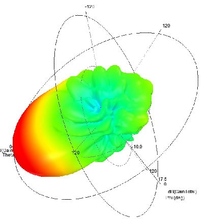
Optimize the Antenna Design Using Simulation Tools
cURL Too many subrequests. cURL Too many subrequests.
cURL Too many subrequests.
cURL Too many subrequests.
cURL Too many subrequests.
cURL Too many subrequests.
cURL Too many subrequests.
cURL Too many subrequests.
cURL Too many subrequests.
cURL Too many subrequests.
cURL Too many subrequests.
cURL Too many subrequests.
cURL Too many subrequests.
cURL Too many subrequests.

cURL Too many subrequests. cURL Too many subrequests. cURL Too many subrequests.
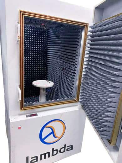
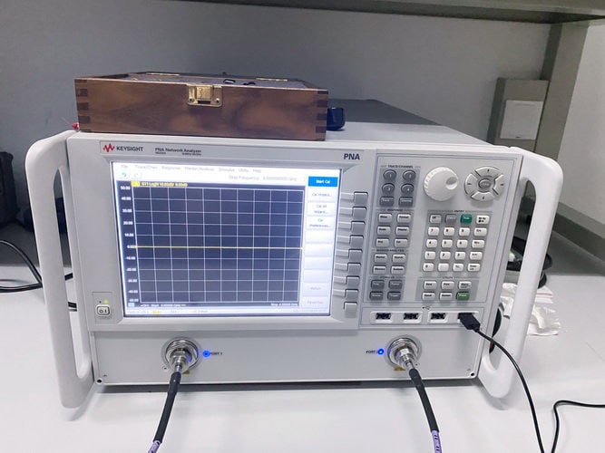
During the demo tests, the antenna is connected to a network analyzer or spectrum analyzer, and the measurements are taken at various frequencies. The gain of the antenna is measured by comparing the power radiated by the antenna in a specific direction to the power radiated by a reference antenna (usually a dipole) in the same direction. Efficiency is measured by comparing the power radiated by the antenna to the power delivered to the antenna.
The beamwidth of the antenna can also be measured during the demo tests. The beamwidth is the angular separation between the points on the radiation pattern where the power is half of the maximum power. A narrow beamwidth indicates a highly directional antenna, while a wide beamwidth indicates a more omnidirectional antenna.
Based on the measurements taken during the demo tests, adjustments can be made to the antenna design. For example, if the gain is lower than expected, the antenna dimensions may need to be adjusted. Similarly, if the beamwidth is too wide or too narrow, changes to the antenna design may be necessary.
By conducting demo tests, engineers can validate the simulation results, identify any discrepancies between the simulated and real-world performance, and make the necessary adjustments to optimize the antenna design.
Ensure Compliance with Regulatory Standards
In conclusion, it is important to follow regulatory standards for electromagnetic emissions and safety when designing an antenna. This is important to ensure legal compliance and to make sure that the antenna does not interfere with other devices. Engineers and technicians need to be aware of these standards and include compliance checks in the design and testing process.
Designing mmWave antennas requires a deep understanding of electromagnetic principles, careful consideration of application requirements, and a meticulous approach to simulation and testing. By following these nine tips, designers can navigate the challenges of mmWave antenna design and develop high-performing antennas for a wide range of applications. Whether you’re a buyer looking to understand the intricacies of mmWave antenna design, a techie/hacker experimenting with 5G technologies, a technician involved in the fabrication process, or an engineer responsible for the end-to-end design, these tips provide a solid foundation for designing mmWave antennas.
1. Understand the Basics of Electromagnetics: Before diving into mmWave antenna design, it’s important to have a good grasp of electromagnetic principles. This includes understanding concepts such as wavelength, frequency, propagation, and polarization.
2. Consider Application Requirements: Different applications have different requirements for mmWave antennas. Consider factors such as frequency range, gain, beamwidth, and polarization when designing an antenna for a specific application.
3. Choose the Right Antenna Type: There are various types of mmWave antennas, including patch antennas, horn antennas, and slot antennas. Each type has its own advantages and disadvantages, so choose the one that best suits your application requirements.
4. Optimize Antenna Dimensions: The dimensions of an mmWave antenna directly affect its performance. Optimize the dimensions to achieve the desired gain, beamwidth, and other parameters.
5. Simulate with EM Field Solvers: Use electromagnetic (EM) field solvers to simulate the performance of your mmWave antenna design. These tools can help you visualize the electric and magnetic fields, as well as calculate parameters such as S-parameters, radiation patterns, and impedance matching.
6. Prototype and Test: Once you have a satisfactory design from simulation, build a prototype and test it. Use vector network analyzers, spectrum analyzers, and other test equipment to measure the performance of the antenna.
7. Refine and Iterate: Based on the results of your testing, refine your design and iterate the process. This may involve adjusting the dimensions, adding or removing components, or changing the antenna type.
8. Consider Manufacturing Constraints: When designing mmWave antennas, it’s important to consider the constraints and limitations of the manufacturing process. This includes the materials used, the fabrication techniques, and the cost.
9. Validate with Real-World Testing: Finally, validate the performance of your mmWave antenna in real-world conditions. This may involve testing it in different environments, with different objects or obstacles, and over different distances.
By following these tips, you can design mmWave antennas that meet the requirements of your application and deliver high performance. Whether you’re designing antennas for 5G networks, automotive radar systems, or other mmWave applications, these principles will help you succeed.