 Skip to content

In an increasingly connected world, the demand for reliable and high-performance communication systems has never been greater. Whether you’re looking to enhance your internet connectivity in remote areas, establish a robust satellite communication link, or simply improve your television reception, a parabolic dish antenna can be an invaluable tool.
cURL Too many subrequests. are renowned for their ability to focus signals, making them ideal for receiving and transmitting data over long distances. Their unique design allows them to capture weak signals and amplify them, providing users with a clearer and more stable connection. However, with a myriad of options available on the market, selecting the right parabolic dish antenna can be a daunting task.
This guide aims to simplify the decision-making process by outlining the key factors to consider when choosing a parabolic dish antenna. From understanding the technical specifications to assessing your specific needs and environment, we will provide you with the insights necessary to make an informed choice. Whether you are a seasoned professional or a novice, this guide will equip you with the knowledge to select the perfect parabolic dish antenna for your requirements.
Importance of parabolic dish antennas in modern communication
Parabolic dish antennas play a crucial role in modern communication systems due to their unique design and functionality. Here are some key points highlighting their importance:
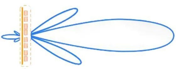
1. High Gain and Directivity: Parabolic dish antennas are designed to focus signals onto a single focal point, which significantly increases their gain and directivity. This allows for effective long-distance communication, making them ideal for point-to-point links, backhaul networks, radio telescopes, and 4G/5G communications.
2. Wide Frequency Range: These antennas can operate across a broad range of frequencies, from microwave to millimeter-wave bands. This versatility makes them suitable for various applications, including satellite TV, internet services, and radar systems.
3. Signal Quality: The focused nature of parabolic antennas minimizes noise and interference, leading to improved signal quality. This is particularly important in applications where data integrity is critical, such as in telecommunications and broadcasting.
4. Space Communication: In satellite communications, parabolic dish antennas are essential for transmitting and receiving signals between ground stations and satellites. Their ability to maintain a strong connection over vast distances is vital for global communication networks.
5. Cost-Effectiveness: While the initial setup of a parabolic dish antenna may involve significant investment, their durability and efficiency often lead to lower long-term operational costs. They require less power to transmit signals compared to other types of antennas, which can lead to savings in energy consumption.
6. Adaptability: Parabolic antennas can be easily adapted for various uses, including mobile applications (like satellite phones and portable internet) and fixed installations (like satellite TV dishes). This adaptability makes them a preferred choice for many industries.
7. Research and Development: In scientific research, parabolic dish antennas are used in radio astronomy and other fields to gather and analyze data from space. Their ability to detect weak signals from distant celestial bodies contributes to advancements in our understanding of the universe.
8. Emerging Technologies: With the rise of technologies such as 5G and the Internet of Things (IoT), parabolic dish antennas are being integrated into new communication infrastructures, providing the necessary bandwidth and connectivity for these advanced systems.
In summary, parabolic dish antennas are integral to modern communication, offering high performance, versatility, and reliability across various applications. Their continued evolution and integration into new technologies underscore their significance in facilitating global connectivity and advancing communication capabilities.
Chapter 1: Understanding Parabolic Dish Antennas
Definition and basic principles
A parabolic dish antenna, commonly referred to as a parabolic antenna, is a type of antenna that uses a parabolic reflector to direct radio waves. This design allows for the efficient transmission and reception of signals, making it widely used in various applications, including WiFi networks, mobile communications, public security and radio telescopes, etc. Here are the key definitions and basic principles associated with parabolic dish antennas:
Definition
A parabolic dish antenna consists of a parabolic-shaped reflector that collects and focuses incoming electromagnetic waves onto a single point known as the feed or feed horn. The shape of the dish allows for the focusing of signals, which enhances the antenna’s gain and directionality.
Basic Principles
1. Parabolic Shape: The parabolic reflector is defined mathematically by the property that any parallel rays coming into the dish (e.g., from a distant satellite) will reflect off the surface and converge at the focus point. This geometric property is essential for directing signals effectively.
2. Focus Point: The feed horn is placed at the focal point of the parabola. When signals hit the dish, they are reflected towards this point, where the feed horn captures the concentrated energy. The placement of the feed horn is crucial for optimizing performance.

3. Gain: Parabolic antennas are known for their high gain, which is a measure of how well the antenna can direct radio waves in a particular direction compared to a standard antenna (like a dipole). The gain is influenced by the size of the dish; larger dishes generally offer higher gain.
4. Directivity: The design of the parabolic dish allows it to focus signals in a specific direction, making it highly directional. This characteristic is beneficial for reducing interference from unwanted signals coming from other directions.
5. Bandwidth: Parabolic antennas can operate over a wide range of frequencies, but their performance can vary with frequency. The bandwidth is determined by the size of the dish and the design of the feed.
Conclusion
Parabolic dish antennas are effective tools for capturing and transmitting electromagnetic signals due to their unique geometric properties. Their ability to focus energy and achieve high gain makes them ideal for a variety of communication and observational applications.
How parabolic dish antennas work
Parabolic dish antennas, often referred to as reflector antennas, are widely used for wireless communications, backhauls, point-to-point links, satellite communications , Telemetry systems and other applications that require the reception or transmission of radio waves. Here’s how they work:
Structure
1. Parabolic Shape: The dish is shaped like a parabola, which is a specific type of curve that has the property of focusing incoming parallel rays (like those from a satellite) to a single point known as the focus.
2. Feedhorn: At the focal point of the parabola, there is a feedhorn(feed) that receives or transmits the signals.

cURL Too many subrequests.
1. Signal Reception:
– Incoming Signals: When radio waves hit the surface of the parabolic dish, they are reflected towards the focal point. The shape of the dish ensures that all incoming parallel signals (from a distant source) are directed to the focus.
– Focusing: The feedhorn at the focal point captures these concentrated signals, which are then converted into electrical signals for processing.
2. Signal Transmission:
– Outgoing Signals: When transmitting signals, the feedhorn emits radio waves that travel outward. The parabolic shape reflects these waves into a parallel beam directed towards the intended target (like a satellite).
cURL Too many subrequests.
Advantages
cURL Too many subrequests.
cURL Too many subrequests.
cURL Too many subrequests.
cURL Too many subrequests.
cURL Too many subrequests.
cURL Too many subrequests.
cURL Too many subrequests.
- cURL Too many subrequests. cURL Too many subrequests.
- cURL Too many subrequests. cURL Too many subrequests.
- cURL Too many subrequests. cURL Too many subrequests.
cURL Too many subrequests.
cURL Too many subrequests.
cURL Too many subrequests.
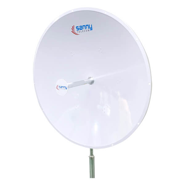
cURL Too many subrequests.
- cURL Too many subrequests.
- For transmissions, the process works in reverse: the feed emits radio waves, which the dish redirects outward in a tight, concentrated beam.
This focused approach offers reliable signal capture, making prime focus antennas a go-to for satellite ground stations and radio telescopes (think Arecibo or telescopes at the VLA) where precision is paramount. However, since the feed sits directly in the signal path, it can block a small portion of incoming or outgoing waves—something engineers have to weigh when designing these systems.
Prime focus antennas are valued for their straightforward geometry and are often chosen when simplicity, robustness, and high performance on a fixed mount are required.
Specialized designs for specific applications
Parabolic dish antennas are highly versatile and can be specialized for various applications, each requiring specific design considerations to optimize performance. Here are some specialized designs for specific applications:
1. Mobile Networks
– Design Features:
– Beamforming Technology: Enhanced signal targeting to improve coverage and reduce interference.
– Compact and Lightweight: Smaller designs suitable for urban deployments and integration with existing infrastructure.
– Applications: 4G/5G network deployment, small cell solutions, and enhancing mobile data transmission.
2. WiFi Communication
– Design Features:
– Directional Antenna Design: Focused signal to extend range and improve performance in specific areas.
– High Gain: Increased gain to enhance signal strength and reduce dead zones.

– Applications: Long-range WiFi links, outdoor networks, and extending coverage in large areas.
3. CCTV Surveillance
– Design Features:
– High Sensitivity: Designed to capture high-resolution video signals even in low-light conditions.
– Weatherproofing: Durable materials and coatings to withstand environmental factors.
– Applications: Security monitoring, traffic surveillance, and perimeter protection.
4. Radio Astronomy
– Design Features:
– Low Noise: Use of low-noise amplifiers (LNAs) to minimize signal degradation.
– Wide Bandwidth: Capable of receiving a broad range of frequencies to capture faint astronomical signals.
– High Precision Tracking: Equipped with advanced tracking systems to follow celestial objects.
– Applications: Observing cosmic phenomena, studying celestial bodies, and collecting data from deep space.
5. Earth Observation
– Design Features:
– Multi-Band Capability: Designed to receive signals across multiple frequency bands for different types of data (optical, radar, etc.).
– High Resolution: Larger dishes for better image resolution and detail.
– Applications: Remote sensing, weather monitoring, and environmental studies.
6. Scientific Research and Testing
– Design Features:
– Variable Aperture: Adjustable dish size to accommodate various experiments.
– Precision Engineering: High-quality materials and construction for minimal distortion.
– Applications: Laboratory experiments, material testing, and engineering research.
7. Military Applications
– Design Features:
– Stealth Design: Coatings and structures to reduce radar cross-section.
– Mobility: Portable designs for quick deployment in various terrains.
– Applications: Secure communications, reconnaissance, and surveillance.
8. Amateur Radio (Ham Radio)
– Design Features:
– Modular Design: Allows for easy upgrades and modifications.
– Cost-Effective Materials: Use of affordable materials for hobbyists.
– Applications: Personal communication, experimentation, and community outreach.
9. Telemetry
– Design Features:
– Real-Time Data Transmission: Capable of transmitting data from remote sensors to a central location with minimal delay.
cURL Too many subrequests.
cURL Too many subrequests.
cURL Too many subrequests.
cURL Too many subrequests.
cURL Too many subrequests.
cURL Too many subrequests.
cURL Too many subrequests.
cURL Too many subrequests.
cURL Too many subrequests. cURL Too many subrequests.
cURL Too many subrequests.
cURL Too many subrequests.
cURL Too many subrequests.
cURL Too many subrequests.
cURL Too many subrequests.
cURL Too many subrequests.
cURL Too many subrequests.
cURL Too many subrequests.
cURL Too many subrequests.
cURL Too many subrequests.
– Applications: Commonly used in specialized applications, including deep-space communication, radio astronomy, and large-scale satellite communication.
– Characteristics: High gain and excellent directivity, allowing for long-distance communication and improved signal reception. They require more robust mounting structures and can be more difficult to install.
These categories help users select the appropriate antenna for their specific needs based on factors like signal strength, distance, and application requirements.
Reflector Shape Styles
Parabolic dish antennas can come in various reflector(dish) shape styles, each designed to optimize performance, weight, and manufacturing costs. Here are the three styles you mentioned:
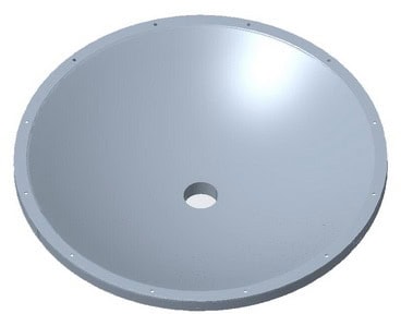
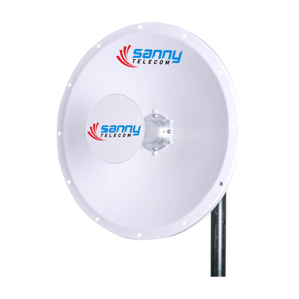
1. Solid Integrated Reflector:
– Description: This style features a solid surface that is typically made from materials like aluminum alloy, copper or steel.
cURL Too many subrequests.
– Provides a smooth, continuous reflective surface that effectively focuses signals to the feed antenna.
– More durable and can withstand harsh environmental conditions, making them suitable for permanent installations.
– Generally offers higher efficiency in signal reflection.
– Disadvantages:
– Tends to be heavier, which may require more robust mounting structures.
– Can be more expensive to manufacture and transport due to the material and weight.
2. Grid Mesh Integrated Reflector:
– Description: Grid mesh reflectors use a lattice or mesh design, which reduces weight while still providing adequate reflective properties.

cURL Too many subrequests.
– Lighter and easier to handle, making them suitable for installations in high-wind areas.
– Allows wind to pass through, reducing the risk of wind loading.
– Typically less expensive to manufacture due to the reduced material usage.
– Disadvantages:
– May have slightly lower efficiency compared to solid reflectors due to gaps in the mesh.
– Can be less durable in certain conditions, depending on the material used.
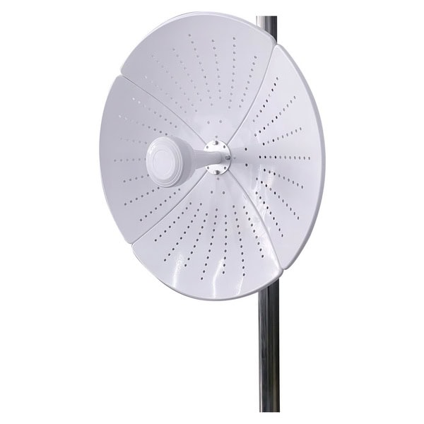
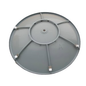
3. Pizza Type Reflector:
– Description: The “pizza type” reflector refers to a design that resembles a pizza shape, often with a flat or slightly curved surface.
cURL Too many subrequests.
– Can have a more shallow profile, making them suitable for applications where space is limited.
– May be optimized for specific frequency ranges, enhancing performance for certain communication needs.
– Can be designed to be lightweight while still providing reasonable performance.
– Disadvantages:
– Performance may vary depending on the specific design and materials used.
– May not offer the same level of durability or efficiency as solid reflectors in all conditions.
Reflector Machining Methods
Parabolic dish antennas require precise shaping of their reflectors to ensure optimal performance. Various machining methods can be employed to create these reflectors, each with its own advantages and disadvantages. Here’s an overview of some common methods:
1. Hydraulic Pressure Forming:
– Description: This method uses hydraulic pressure to shape metal sheets into the desired parabolic form. Tooling/mold: A custom mold is required to define the parabolic shape.

– Advantages: It allows for the creation of complex shapes with a high degree of accuracy and smooth surfaces. It can handle large sheets of material.
– Disadvantages: The initial tooling can be costly and much higher than spinning and stamping.
2. Spinning:
– Description: In spinning, a metal disc is rotated at high speeds while being pressed against a form to create a dish shape. Tooling/mold: A spinning mandrel or form is needed to achieve the desired parabolic contour.

– Advantages: This method is suitable for producing lightweight, thin-walled components with good surface finish and minimal waste, as well as lower tooling cost to begin with.
– Disadvantages: The process may be slower compared to other methods and the machining cost is higher than Hydraulic Pressure Forming for mass production.
3. Die-casting:
– Description: This method involves pouring molten metal(aluminum alloy) into a mold to create the desired shape. Tooling/mold: A custom die is required for each specific parabolic design.

– Advantages: It allows for high-volume production and can create complex geometries with excellent surface finishes.
– Disadvantages: The reflector has to be a pizza style, and the initial cost of molds can be high. And the unit price is also higher than other machining methods.
cURL Too many subrequests.
cURL Too many subrequests.

cURL Too many subrequests.
cURL Too many subrequests.
cURL Too many subrequests.
cURL Too many subrequests.

cURL Too many subrequests.
cURL Too many subrequests.
cURL Too many subrequests.
cURL Too many subrequests.
cURL Too many subrequests.
cURL Too many subrequests.
cURL Too many subrequests.
cURL Too many subrequests.

cURL Too many subrequests.
cURL Too many subrequests.
cURL Too many subrequests.
Feedhorn
cURL Too many subrequests.
cURL Too many subrequests.
– Design: A waveguide feedhorn consists of a hollow metallic structure that guides electromagnetic waves. The feedhorn is typically attached to the focal point of the parabolic dish.
– Functionality: It efficiently directs the incoming signals from the dish to the receiver or vice versa, minimizing losses.
cURL Too many subrequests.
– Low Loss: Waveguides have lower signal loss compared to coaxial feeds, especially at higher frequencies.
– High Power Handling: They can handle higher power levels without significant distortion.
– Reduced Interference: The design minimizes unwanted coupling and interference from external signals.
– Applications: Commonly used in microwave and satellite communications where high performance is required.
2. Coaxial Feed
– Design: A coaxial feed consists of a central conductor surrounded by a dielectric insulator and an outer conductor. The feedhorn often comes out with short pigtails such as 30cm RG58.
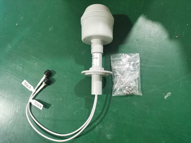
– Functionality: Signals are transmitted through the coaxial cable, and the feedhorn converts these signals into a form that can be effectively collected by the dish.
cURL Too many subrequests.
– Ease of Installation: Coaxial feeds are generally easier to install and integrate with existing systems.
– Cost-Effective: They tend to be less expensive than waveguide feeds.
– Flexibility: Coaxial cables can be easily routed and are available in various lengths and configurations.
– Applications: Often used in consumer satellite dishes and some radio applications where high power and low loss are less critical.
cURL Too many subrequests.
The choice between a waveguide feedhorn and a coaxial feedhorn largely depends on the specific requirements of the application, such as frequency, power handling, installation considerations, and budget. Waveguide feeds are preferred for high-performance applications, while coaxial feeds are suitable for more general use cases.
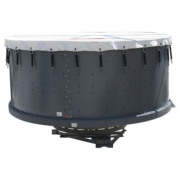
Protection Radome
A protection radome is a structural enclosure that shields antennas, particularly parabolic dish antennas, from environmental factors such as wind, rain, snow, and debris while allowing radio waves to pass through with minimal interference. Radomes are typically made from materials that are transparent to electromagnetic signals, such as fiberglass or certain types of plastics.

Key Features of Protection Radomes:
1. Material Composition: Radomes are crafted from materials that have low dielectric loss and are lightweight yet durable. Common materials include:
– Fiberglass
Fiberglass is a widely used material in the construction of radomes due to its excellent combination of properties. It is lightweight, strong, and has low dielectric loss, making it ideal for applications that require minimal signal attenuation. Fiberglass can be molded into various shapes and sizes, allowing for versatile designs in radome construction. Additionally, it is resistant to environmental factors such as UV radiation and moisture, contributing to the durability and longevity of radomes in outdoor applications. Overall, fiberglass is a popular choice for radomes in both commercial and military communication systems.
– ABS
ABS (Acrylonitrile Butadiene Styrene) can also be used in the construction of radomes, particularly for applications where impact resistance and durability are important. While it may not have the same low dielectric loss characteristics as materials like PTFE or fiberglass, ABS can be a suitable choice for certain environments due to its strength and ease of molding. However, it is essential to consider the specific requirements of the application, such as temperature stability and dielectric properties, when selecting materials for radome construction.
Polycarbonate is another valuable material used in the construction of radomes. It is known for its high impact resistance, toughness, and transparency, which allows for excellent visibility of antennas while providing protection from environmental elements. Polycarbonate is lightweight, making it suitable for applications where weight savings are critical.
In terms of dielectric properties, polycarbonate offers moderate performance, though it may not match the low dielectric loss characteristics of materials like PTFE. However, its ability to withstand extreme temperatures and its resistance to UV radiation make it an effective choice for outdoor applications.
Additionally, polycarbonate can be easily molded into various shapes and sizes, allowing for versatile designs in radome construction. Overall, polycarbonate is a practical option for radomes in various settings, balancing performance, durability, and cost-effectiveness.
– PTFE (Teflon)
PTFE (Polytetrafluoroethylene), commonly known by the brand name Teflon, is another excellent material for radome construction. It is renowned for its very low dielectric loss, which makes it highly effective in minimizing signal attenuation. PTFE also exhibits remarkable chemical resistance, thermal stability, and non-stick properties, making it suitable for a variety of environmental conditions.
In addition to its electrical properties, PTFE is lightweight and can be fabricated into complex shapes, allowing for effective radome designs that protect antennas while maintaining optimal performance. Its durability and resistance to environmental degradation make PTFE a preferred choice for high-performance radomes used in both commercial and military applications, especially in harsh conditions.
2. Design: The design of a radome must ensure that it does not significantly distort the antenna’s radiation pattern. This often involves a careful consideration of the shape, thickness, and surface smoothness.
3. Environmental Protection: Radomes provide protection against:
– Weather elements (rain, snow, ice)
– UV radiation
– Wind loads
– Physical impacts (debris, birds)
4. Performance: A well-designed radome will have minimal impact on the antenna’s performance, maintaining high signal integrity and minimizing signal loss.
5. Installation: Proper installation is crucial to ensure that the radome does not interfere with the antenna’s operation. It should be securely mounted and aligned with the antenna’s aperture.
6. Maintenance: Regular inspection and maintenance may be required to ensure that the radome remains clear of obstructions (like ice or debris) and that the materials do not degrade over time.
In summary, protection radomes are essential for safeguarding antennas against environmental challenges while preserving their operational efficiency.
Mounting Brackets
When selecting mounting brackets for parabolic dish antennas, it’s important to consider the weight and size of the antenna, as well as the environmental conditions where it will be installed. Here are some options:
cURL Too many subrequests.
cURL Too many subrequests.
cURL Too many subrequests.

cURL Too many subrequests.
cURL Too many subrequests.
cURL Too many subrequests.
cURL Too many subrequests.
cURL Too many subrequests.
cURL Too many subrequests.
cURL Too many subrequests.
cURL Too many subrequests.

cURL Too many subrequests.
cURL Too many subrequests.
cURL Too many subrequests.
cURL Too many subrequests.
cURL Too many subrequests.
cURL Too many subrequests.
cURL Too many subrequests.
cURL Too many subrequests.
cURL Too many subrequests.
– Local Regulations: Check for any local regulations or guidelines regarding antenna installations.
Additional Accessories
– Anti-Rotation Features: Some brackets come with features to prevent the antenna from rotating in high winds,especially for size larger than 0.9m.

– Cable Management: Consider brackets that provide options for securing and managing cables to prevent tangling and damage.
By choosing the appropriate mounting bracket based on the size and weight of your parabolic dish antenna, you can ensure a stable and effective installation.
Chapter 3: Key Factors in Antenna Selection
Frequency bands
Parabolic dish antennas can be classified based on the frequency bands they operate within. These classifications are important for various applications, including telecommunications, broadcasting, and satellite communications. Here are the common frequency bands associated with parabolic dish antennas:
1. L-Band (1 to 2 GHz)
– Commonly used for satellite communications, GPS, and some mobile communications.
2. LTE Bands (1710 to 2700 MHz)
– Used for mobile telecommunications and data services.
3. S-Band (2 to 4 GHz)
– Used for weather radar, some satellite communications, and certain wireless communication systems.
4. 5G Mid-bands (3300 to 4000 MHz)
– Used for next-generation mobile telecommunications, providing higher data rates and lower latency.
5. WiFi Bands

– 2.4 GHz (2.4-2.5GHz): Commonly used for WiFi networks and other wireless communication.
– 5 GHz (5.15-5.85GHz): Used for WiFi networks, providing higher speeds and less interference than 2.4 GHz.
– 6 GHz (5.925-7.125GHz): An emerging band for WiFi, offering additional bandwidth and reduced congestion.
6. 5.09 to 5.25 GHz
– Used for specific communication applications, including Telemetry systems, some WiFi and wireless communication systems.
7. C-Band (4 to 8 GHz)
– Widely used for satellite communications, including television broadcasting and data transmission.
– Includes the frequency range of 4.4 to 5.0 GHz, which is used for various communication applications.
Each frequency band has its advantages and disadvantages, including factors like bandwidth, propagation characteristics, and susceptibility to atmospheric attenuation. The choice of frequency band for a parabolic dish antenna depends on the specific application and operational requirements.
Gain and Focal Length
The gain of a parabolic dish antenna is a measure of its ability to focus energy in a particular direction, and it is closely related to the physical characteristics of the antenna, including its size and focal lengt
cURL Too many subrequests.
The gain (G) of a parabolic dish antenna can be expressed in decibels (dB) using the following formula:
G(dB) = 10 · log10 (4 π A_e / λ²)
Where:
– A_e is the effective aperture area of the antenna, which for a parabolic dish can be approximated as:
A_e = π D² / 4
where D is the diameter of the dish.
– λ is the wavelength of the signal being transmitted or received.
Focal Length
The focal length (f) of a parabolic dish is the distance from the vertex of the parabola to the focal point. The relationship between the diameter (D) of the dish and its focal length can be described by the following formula:
f = D² / (16h)
Where h is the depth of the dish. This relationship indicates that the focal length is dependent on the geometry of the dish.
Relationship Between Gain and Focal Length
While gain is primarily influenced by the size of the dish (diameter) and the wavelength, the focal length can impact the design and efficiency of the antenna. A well-designed parabolic dish with an appropriate focal length will effectively focus the incoming waves onto the feed antenna, maximizing gain.
In practice, a larger dish (greater diameter) will generally yield a higher gain, while the focal length must be optimized to ensure that the feed is positioned correctly to capture the focused energy.
cURL Too many subrequests.
– Gain is influenced by the effective aperture area, which is determined by the diameter of the dish and the wavelength of the signal.
cURL Too many subrequests.
cURL Too many subrequests.
cURL Too many subrequests.
Definition
cURL Too many subrequests.
cURL Too many subrequests.

Importance
cURL Too many subrequests.
cURL Too many subrequests.
cURL Too many subrequests.
cURL Too many subrequests.
cURL Too many subrequests.
cURL Too many subrequests.
Polarization
Definition
cURL Too many subrequests.
Importance
cURL Too many subrequests.
cURL Too many subrequests.
cURL Too many subrequests.
cURL Too many subrequests.
cURL Too many subrequests.
cURL Too many subrequests.
cURL Too many subrequests.
cURL Too many subrequests.
cURL Too many subrequests.
– Slant Polarization: The electric field is oriented at an angle to the ground, typically at 45 degrees, providing a compromise between vertical and horizontal polarization.

2. Circular Polarization: The electric field rotates in a circular motion as the wave propagates. It can be:
– Right-Hand Circular Polarization (RHCP): The electric field rotates clockwise when viewed from the receiver towards the source.
– Left-Hand Circular Polarization (LHCP): The electric field rotates counterclockwise under the same viewing conditions.
3. Elliptical Polarization: A general form of polarization where the electric field describes an ellipse. This can be considered as a combination of linear and circular polarization.
4. Dual Polarization: This involves the use of two different polarizations simultaneously, typically linear (vertical and horizontal) or circular (RHCP and LHCP). It allows for improved signal reception and transmission by utilizing both polarizations to enhance data throughput and reduce interference.

Understanding these types of polarization is essential for effective communication and signal transmission in various applications involving parabolic dish antennas.
cURL Too many subrequests.
Definition
Voltage Standing Wave Ratio (VSWR) is a measure of how efficiently radio frequency (RF) power is transmitted from a power source, through a transmission line, and into a load (such as an antenna). It is defined as the ratio of the maximum voltage to the minimum voltage along the transmission line. A VSWR of 1:1 indicates perfect matching, where all the power is transferred to the load without any reflection, while higher values indicate increasing levels of reflected power due to impedance mismatches.

Importance
1. Efficiency: A low VSWR indicates that most of the power is being effectively transmitted to the antenna, which is crucial for maximizing the efficiency of the communication system.
2. Performance: High VSWR can lead to reduced performance of the antenna system, including decreased range and signal quality. This is particularly important in applications such as satellite communications, where parabolic dish antennas are used.
3. Equipment Protection: Excessive reflected power due to high VSWR can damage RF components, such as transmitters and amplifiers, leading to costly repairs and downtime.
4. System Optimization: Monitoring VSWR helps in tuning and optimizing the antenna system for better performance and ensuring that the entire RF system operates within its designed specifications.
Acceptable VSWR Values for Efficient Operation
– 1.0:1: Ideal condition where there is no reflected power and perfect impedance matching.
– 1.1:1 to 1.5:1: Generally considered excellent; minimal reflected power, and the system operates efficiently.
– 1.5:1 to 2.0:1: Acceptable for most applications; some reflected power, but still within tolerable limits for efficient operation.
In summary, maintaining a low VSWR is critical for the efficient operation of parabolic dish antennas and other RF systems, ensuring optimal performance and longevity of equipment.
F/B (Front-to-back ratio)
Definition
The Front-to-Back Ratio (F/B Ratio) of a parabolic dish antenna is a measure of how well the antenna can discriminate between signals coming from the front (the direction it is pointed) versus signals coming from the back (the opposite direction). It is defined as the ratio of the power received from the front to the power received from the back, usually expressed in decibels (dB). A higher F/B ratio indicates better performance in rejecting unwanted signals from the rear.
Importance
1. Signal Clarity: A high F/B ratio helps in reducing interference from signals that originate from the back of the antenna, leading to a clearer and more reliable signal reception.
2. Improved Communication: In applications such as satellite communications, broadcasting, and point-to-point links, a good F/B ratio ensures that the desired signal is much stronger than any unwanted signals, improving overall communication quality.
3. Enhanced Directionality: The F/B ratio is an indicator of the antenna’s directivity. A high F/B ratio typically means that the antenna is more directional, focusing energy in the intended direction and minimizing reception from other directions.
4. Application Suitability: Different applications may require different F/B ratios. Understanding the F/B ratio helps in selecting the right antenna for specific uses, such as telecommunications, radar, or broadcasting.
Acceptable F/B Values
The acceptable F/B values can vary depending on the application and the design of the antenna. However, general guidelines include:
– Typical Values: For most parabolic dish antennas, an F/B ratio of 20 dB to 40 dB is common. This range indicates a reasonable level of front-to-back discrimination.
– High-Performance Applications: In applications where interference is a significant concern, such as in crowded frequency environments or in satellite communications, F/B ratios of 20 dB to 30 dB or higher may be desirable.
– Lower-End Values: For some low-cost or less critical applications, F/B ratios below 10 dB may be acceptable, but this could lead to more interference and reduced signal quality.
In summary, while the acceptable F/B ratio can vary based on specific needs and applications, a higher F/B ratio is generally preferred for better performance in signal discrimination and overall communication quality.
ISO(Isolation)
Definition
Isolation in the context of parabolic dish antennas refers to the degree to which the antenna can reject or minimize interference from unwanted signals, particularly from adjacent antennas or other sources of electromagnetic interference. It is typically measured in decibels (dB) and indicates how effectively the antenna can isolate a desired signal from other signals in the environment.

Importance
1. Signal Quality: High isolation improves the quality of the received signal by reducing noise and interference, which is crucial for applications such as satellite communications and broadcasting.
2. System Performance: Isolation helps maintain the integrity of the communication system, ensuring that the desired signals are received clearly without degradation from other signals.
3. Multi-User Environments: In scenarios where multiple antennas operate in close proximity (e.g., satellite ground stations), adequate isolation is essential to prevent crosstalk and interference.
4. Regulatory Compliance: Many communication systems must meet specific isolation standards to comply with regulatory requirements, ensuring that they do not disrupt other services.
5. Operational Reliability: High isolation contributes to the overall reliability of the communication link, reducing the likelihood of dropped signals or communication failures.
Acceptable Isolation Values
Acceptable isolation values can vary depending on the specific application and frequency band. However, general guidelines are as follows:
– For Satellite Communication: Isolation values of 20 dB or higher are often considered acceptable, with 30 dB or more being ideal for high-performance systems.
– For Terrestrial Communication: Isolation values can range from 15 dB to 30 dB, depending on the proximity of other transmitting antennas and the frequency used.
– For Multi-User Systems: Values of 25 dB or higher are typically sought to ensure minimal interference between multiple users.
It’s important to consult specific industry standards or guidelines relevant to the application to determine the exact acceptable isolation values for a particular parabolic dish antenna system.
Antenna Size and Weight
When considering parabolic dish antennas, both physical constraints and mounting considerations play a crucial role in their design, transportation, and installation. Here’s a breakdown of these factors:
Physical Constraints and Mounting Considerations
1. Size and Weight:
cURL Too many subrequests.
cURL Too many subrequests.
cURL Too many subrequests.
cURL Too many subrequests.
cURL Too many subrequests.
cURL Too many subrequests.
cURL Too many subrequests.
cURL Too many subrequests.
cURL Too many subrequests.
5. Environmental Considerations:
cURL Too many subrequests.
cURL Too many subrequests.
cURL Too many subrequests.
cURL Too many subrequests.

cURL Too many subrequests.
cURL Too many subrequests.
cURL Too many subrequests.
cURL Too many subrequests.
cURL Too many subrequests.
cURL Too many subrequests.
– Training may be necessary for installation teams to ensure proper alignment and safety procedures.
4. Regulatory and Permitting Issues:
– Depending on the size and location, installation may require permits or adherence to local regulations, which can impact timelines and costs.
– Environmental assessments may also be necessary, especially for large installations.
5. Maintenance Access:
– Consideration should be given to future maintenance needs. Dishes may require regular cleaning, adjustments, or repairs, necessitating easy access without compromising the integrity of the installation.
Conclusion
The design, transportation, and installation of parabolic dish antennas are significantly influenced by physical constraints and mounting considerations. Careful planning and execution can mitigate challenges, ensuring efficient operation and longevity of the antenna system.
Environmental Considerations
When considering the environmental aspects of parabolic dish antennas, several factors are critical to ensure their longevity and optimal performance. Here’s a breakdown of key considerations:
Weatherproofing and Durability
1. Material Selection: Use materials that are resistant to corrosion and UV degradation. Common materials include galvanized steel, aluminum, and high-grade plastics for the feedhorn and other components.
2. Coatings: Apply protective coatings such as powder coating or anodizing to prevent rust and enhance durability against environmental stressors.
3. Sealing: Ensure that joints and connections are properly sealed to prevent water ingress. Gaskets and weatherproof enclosures can protect sensitive electronic components.
4. Structural Integrity: Design the antenna to withstand high winds and heavy precipitation. This may involve reinforcing the structure and using guy wires or other support systems.
5. Mounting: Use robust mounting systems that can handle vibrations and shifting from environmental factors like wind or seismic activity.
cURL Too many subrequests.
1. Operating Temperature Range: Select components that can operate effectively within the expected temperature range for the installation site. This includes the feedhorn, LNB (Low Noise Block downconverter), and any electronic control systems.
2. Thermal Expansion: Consider the effects of thermal expansion and contraction on materials. Use flexible mounting systems or expansion joints to accommodate these changes.
3. Humidity Resistance: Use moisture-resistant materials and ensure that electronic components are rated for high humidity environments. This may involve using conformal coatings on circuit boards to protect against moisture.
4. Condensation Prevention: Design the antenna system to minimize the chances of condensation forming inside any enclosures. This may include ventilation or heating elements in extreme conditions.
Additional Considerations
1. Lightning Protection: Install lightning rods or grounding systems to protect the antenna from lightning strikes, especially in areas prone to thunderstorms.
2. Wildlife Protection: Consider measures to deter birds and other wildlife that may nest on or around the antenna, as this can obstruct signals and cause damage.
3. Maintenance Accessibility: Design the installation to allow for easy access for maintenance and inspections. This is crucial for ensuring the long-term performance of the antenna.
4. Regulatory Compliance: Ensure that the installation complies with local regulations regarding environmental impact, including any necessary permits for installation in certain areas.
5. Environmental Impact: Assess the potential environmental impact of the installation, including visual impact and effects on local wildlife, and take steps to mitigate any negative effects.
By addressing these environmental considerations, parabolic dish antennas can be effectively protected against the elements, ensuring reliable performance and longevity in various conditions.
Chapter 4: Applications of Parabolic Dish Antennas
WiFi Networks
cURL Too many subrequests. can be effectively used in WiFi networks, particularly in specific scenarios where enhanced signal strength and directionality are required. Here are some applications of parabolic dish antennas in WiFi networks:
1. Long-Distance WiFi Links: Parabolic dish antennas can be used to establish long-range WiFi connections between two points. This is particularly useful for connecting buildings in a campus, linking remote locations, or providing internet access in rural areas.
2. Point-to-Point Communication: For organizations needing to connect two fixed locations, such as offices or buildings, parabolic dishes can provide a reliable and high-speed point-to-point wireless link.
3. Directional Coverage: The highly directional nature of parabolic antennas allows them to focus the WiFi signal in a specific direction, reducing interference from other sources and increasing the effective range. This is beneficial in crowded environments or urban areas with many competing signals.
4. Backhaul Links: In a network with multiple access points, parabolic antennas can serve as backhaul links, connecting access points to a central router or internet source over long distances.
5. Outdoor WiFi Networks: Parabolic dish antennas are suitable for outdoor WiFi installations, especially in areas where the signal needs to penetrate obstacles or cover large open spaces, such as parks or campuses.
6. Mesh Networks: In a mesh network setup, parabolic antennas can be used to connect nodes that are far apart, helping to extend the network range and improve overall performance.
7. Security and Surveillance: In security applications, parabolic antennas can be used to provide WiFi connectivity for cameras and sensors positioned at a distance from the main network infrastructure.
8. Event Connectivity: For temporary events or festivals, parabolic antennas can be deployed to provide reliable WiFi connectivity over large areas, ensuring that visitors have access to the internet.
9. Research and Development: In academic or research settings, parabolic dish antennas can be used to study signal propagation, antenna design, and wireless communication technologies.
10. Disaster Recovery: In emergency situations, parabolic antennas can be set up quickly to establish communication links in areas where traditional infrastructure has been damaged.
While parabolic dish antennas offer significant advantages in terms of range and signal quality, they also require careful alignment and positioning to ensure optimal performance. Additionally, their directional nature means that they are less suitable for general-purpose WiFi coverage in environments where users are spread out in multiple directions.
5G Networks
Parabolic dish antennas are increasingly being utilized in 5G networks due to their ability to focus signals and provide high gain, which is essential for achieving the high data rates and low latencies that 5G technology promises. Here are some key applications of parabolic dish antennas in 5G networks:

1. Backhaul Connectivity: Parabolic dish antennas are often used for backhaul connections in 5G networks. They can connect remote cell sites to the core network, providing high-capacity links that are necessary for transmitting large amounts of data.
2. Fixed Wireless Access (FWA): Parabolic dishes can be deployed for fixed wireless access, allowing internet connectivity to homes and businesses in areas where laying fiber optic cables is impractical or too expensive. They can provide high-speed internet access by connecting directly to 5G base stations.
cURL Too many subrequests.
cURL Too many subrequests.
cURL Too many subrequests.
cURL Too many subrequests.
cURL Too many subrequests.
cURL Too many subrequests.
CCTV
cURL Too many subrequests.
cURL Too many subrequests.
cURL Too many subrequests.
cURL Too many subrequests.
cURL Too many subrequests.
cURL Too many subrequests.
cURL Too many subrequests.
cURL Too many subrequests.
cURL Too many subrequests.
cURL Too many subrequests.
Telemetry
Telemetry cURL Too many subrequests.

cURL Too many subrequests.
2. Remote Sensing: In environmental monitoring, parabolic antennas can be used to receive telemetry data from remote sensing satellites, which gather information about the Earth’s surface, atmosphere, and oceans.
3. Weather Monitoring: Meteorological satellites use parabolic antennas to transmit telemetry data regarding weather conditions, atmospheric pressure, temperature, and other critical parameters back to ground stations.
4. Scientific Research: Various research projects, such as those involving oceanography or climate studies, utilize telemetry data transmitted via parabolic antennas to gather data from buoys, drones, or other remote sensors.
5. Military Applications: In defense, parabolic dish antennas are employed for telemetry in various systems, including missile tracking, reconnaissance, and battlefield communication systems.
6. Telecommunications: In telecommunications, parabolic antennas are used for telemetry in monitoring and controlling network performance, managing signal integrity, and ensuring efficient data transmission.
7. Automotive Testing: In the automotive industry, telemetry systems equipped with parabolic antennas are used to collect data from test vehicles to monitor performance metrics during testing.
8. Aerospace Testing: Parabolic antennas are utilized in telemetry for aircraft and drone testing, allowing engineers to receive real-time data on flight performance and system health.
Overall, the high directivity and gain of parabolic dish antennas make them ideal for applications where reliable and high-quality telemetry data transmission is crucial.
Military and defense applications
Parabolic dish antennas have several critical applications in military and defense sectors due to their high directivity and ability to focus signals. Here are some key applications:

1. Communication Systems: Parabolic dish antennas are widely used in military communication systems for secure, long-range communication. They can facilitate satellite communications, allowing troops in remote locations to maintain contact with command centers.
2. Surveillance and Reconnaissance: These antennas are employed in radar systems for surveillance and reconnaissance missions. They can detect and track aircraft, missiles, and other objects, providing real-time data for strategic decision-making.
3. Targeting and Fire Control: In weapon systems, parabolic antennas are used for targeting and fire control, enhancing the accuracy of missile guidance systems and artillery.
4. Electronic Warfare: Parabolic dish antennas can be utilized in electronic warfare to intercept and jam enemy communications. Their ability to focus on specific frequencies makes them effective for these purposes.
5. Remote Sensing: Military operations often rely on remote sensing technologies for intelligence gathering. Parabolic antennas are integral to satellite-based remote sensing systems that provide imagery and data about enemy positions and movements.
6. Ground-Based Radar Systems: Ground-based radar systems often use parabolic dishes to provide long-range detection capabilities, which are vital for air defense and monitoring of hostile activities.
7. Unmanned Aerial Vehicles (UAVs): Parabolic antennas are used in UAVs for communication links and data transmission, allowing for real-time video feeds and telemetry data to be sent back to operators.
8. Space-Based Systems: Military satellites equipped with parabolic antennas are used for various applications, including reconnaissance, communication, and navigation, enhancing operational capabilities.
9. Signal Intelligence (SIGINT): These antennas are essential in SIGINT operations, where they are used to intercept and analyze electronic communications for intelligence purposes.
10. Training and Simulation: In military training environments, parabolic antennas can be used in simulation systems to create realistic communication scenarios, helping personnel to prepare for real-world operations.
Overall, the versatility and effectiveness of parabolic dish antennas make them indispensable in modern military and defense operations.
Chapter 5: Installation and Setup
Mounting options (ground mount, roof mount, pole mount)
When it comes to mounting parabolic dish antennas, there are several options to consider, each with its own advantages and disadvantages. Here are the most common mounting options:
1. Ground Mount
Description: A ground mount involves installing the antenna directly on the ground, typically using a sturdy pole or a concrete base.

Advantages:
– Stability: Ground mounts are usually very stable and can withstand strong winds.
– Height Adjustment: They can be adjusted to achieve the optimal elevation angle.
– Easy Access: Ground-mounted antennas are generally easier to access for maintenance and alignment.
Disadvantages:
– Space Requirement: Requires sufficient ground space, which may not be available in urban areas.
– Obstructions: Nearby trees, buildings, or other structures may obstruct the signal.
2. Roof Mount
Description: A roof mount involves installing the antenna on the roof of a building, typically using a mounting bracket or pole.

Advantages:
– Height Advantage: Elevation can reduce obstructions and improve signal quality.
– Space Efficiency: Saves ground space, making it ideal for urban settings.
– Less Affected by Ground Interference: Being elevated can help minimize interference from ground-level obstacles.
Disadvantages:
– Installation Complexity: May require professional installation, especially for larger dishes.
– Potential Roof Damage: Installation can risk damaging the roof or voiding warranties.
– Access Issues: Maintenance may require ladders or scaffolding.
3. Pole Mount
Description: A pole mount involves attaching the antenna to a standalone pole, which can be installed in various locations, including the ground or on a roof.

Advantages:
cURL Too many subrequests.
cURL Too many subrequests.
cURL Too many subrequests.
Disadvantages:
cURL Too many subrequests.
cURL Too many subrequests.
cURL Too many subrequests.
Conclusion
cURL Too many subrequests.
cURL Too many subrequests.
cURL Too many subrequests.
cURL Too many subrequests.
cURL Too many subrequests.
cURL Too many subrequests.
cURL Too many subrequests.
cURL Too many subrequests.
cURL Too many subrequests.
cURL Too many subrequests.
cURL Too many subrequests.
cURL Too many subrequests.

cURL Too many subrequests.
cURL Too many subrequests.
– Initial Setup: Adjust the dish to the calculated elevation angle using the scale marked on the mounting bracket.
– Signal Optimization: Similar to azimuth adjustment, make small tweaks by tilting the dish up or down while observing the signal strength. Aim for the highest signal quality.
– Secure the Position: Once the optimal elevation is achieved, tighten the elevation adjustment bolts to prevent movement.
General Tips
– Clear Line of Sight: Ensure there are no obstructions (trees, buildings) blocking the path between the dish and the signal source.
– Use a Signal Meter: A dedicated signal strength meter can provide more accurate readings than a receiver alone.
– Weather Considerations: Be mindful of weather conditions, as rain or snow can affect signal quality. Adjustments may be necessary during inclement weather.
– Regular Maintenance: Periodically check the alignment to ensure optimal performance, especially after severe weather events or physical disturbances.
By following these techniques, you can effectively align a parabolic dish antenna for optimal signal reception.
Safety considerations and regulatory compliance
When dealing with parabolic dish antennas, safety considerations and regulatory compliance are crucial to ensure safe operation and adherence to legal standards. Here are some key points to consider:
Safety Considerations
1. Structural Integrity: Ensure that the dish and its mounting structure are stable and capable of withstanding environmental factors such as wind, snow, and ice. Regular inspections should be performed to identify any wear or damage.
2. Electrical Safety: Proper grounding of the antenna and associated equipment is essential to prevent electrical hazards. Use weatherproof connectors and cables to reduce the risk of short circuits and electrical fires.
3. Radiation Exposure: While parabolic dish antennas typically operate in non-ionizing frequency ranges, ensure that the installation complies with safety guidelines to minimize exposure to RF radiation, especially for personnel working nearby.
4. Installation Safety: When installing antennas at height, follow proper safety protocols, including the use of harnesses, ladders, and scaffolding. Ensure that all personnel involved in the installation are trained in safety practices.
5. Interference with Aircraft: Antennas located near airports or flight paths must be installed in a way that minimizes the risk of interference with aviation communications and navigation systems.
Regulatory Compliance
1. FCC Regulations (USA): In the United States, parabolic dish antennas must comply with the Federal Communications Commission (FCC) regulations regarding emissions and interference. This includes obtaining the necessary licenses for operation, especially for satellite dishes and other communication systems.
2. Local Zoning Laws: Check local zoning regulations and building codes before installation. Some areas may have restrictions on the height and placement of antennas, particularly in residential neighborhoods.
3. Environmental Regulations: Ensure compliance with any environmental regulations that may apply, especially if the installation site is near protected lands or habitats. This may involve assessments to evaluate the potential impact on wildlife and ecosystems.
4. International Regulations: If operating in multiple countries, be aware of the different regulatory frameworks governing telecommunications and broadcasting, including compliance with ITU (International Telecommunication Union) standards.
5. Licensing: Depending on the application (e.g., commercial broadcasting, private use, or amateur radio), specific licenses may be required. Ensure that all necessary permits are obtained before installation and operation.
Conclusion
Adhering to safety considerations and regulatory compliance is vital when working with parabolic dish antennas. It helps protect personnel, the public, and the environment while ensuring lawful and effective use of the technology. Always consult relevant guidelines and authorities to stay informed about the latest regulations and best practices.
Chapter 6: Future Trends in Parabolic Dish Antennas
Advancements in antenna technology
Advancements in antenna technology, particularly for parabolic dish antennas, are being driven by several key trends and innovations. Here are some of the notable developments:
1. Material Innovations: The use of lightweight and durable materials, such as carbon fiber and advanced composites, is helping to reduce the weight of parabolic dishes while maintaining structural integrity. This makes installation easier and allows for larger dishes to be deployed in various environments.
2. Multi-band and Wideband Capabilities: New designs are enabling parabolic antennas to operate across multiple frequency bands simultaneously. This is particularly useful for applications in satellite communications and broadband services, allowing for more versatile and efficient use of bandwidth.
3. Software-Defined Antennas: The integration of software-defined technology is enabling parabolic dish antennas to adapt their characteristics dynamically. This allows for reconfiguration based on changing signal requirements, improving performance and efficiency.
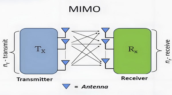
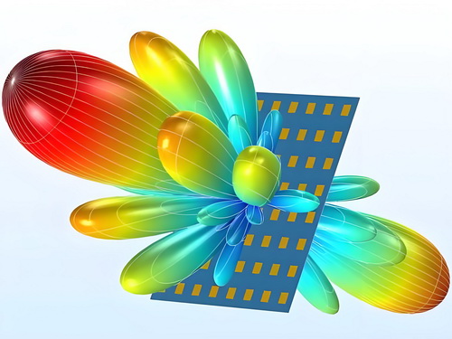
4. Beamforming and MIMO Technology: Advances in beamforming techniques and Multiple Input Multiple Output (MIMO) technology are enhancing the performance of parabolic antennas. These technologies allow for more precise targeting of signals and improved data throughput, which is crucial for applications like 5G and beyond.
5. Integration with IoT: As the Internet of Things (IoT) continues to grow, parabolic antennas are being designed to integrate seamlessly with IoT devices. This includes the ability to communicate with a larger number of devices while maintaining high data rates.
6. Automated Tracking Systems: Enhanced tracking systems that utilize GPS and other technologies are improving the ability of parabolic dishes to maintain alignment with satellites or other communication sources. This is particularly important for mobile applications and low Earth orbit (LEO) satellite systems.
7. Smart Antenna Technology: The development of smart antennas that can adjust their orientation and focus based on real-time data is making parabolic dishes more effective. These systems can optimize signal reception and transmission dynamically, enhancing overall performance.

8. Sustainable Design Practices: There is a growing emphasis on sustainability in antenna design, with a focus on energy efficiency and the use of environmentally friendly materials. This trend aligns with broader efforts to reduce the carbon footprint of telecommunications infrastructure.
9. Miniaturization: Advances in technology are allowing for the miniaturization of parabolic antennas without sacrificing performance. This is particularly beneficial for consumer applications, such as satellite TV and internet services, where compact designs are preferred.
10. Enhanced Signal Processing: Improved signal processing algorithms and hardware are enabling better noise reduction, interference cancellation, and overall signal integrity for parabolic dish antennas. This leads to more reliable communications, especially in challenging environments.
These advancements are making parabolic dish antennas more versatile, efficient, and capable of meeting the growing demands of modern communication systems, including satellite communications, wireless networks, and IoT applications.
Integration with emerging communication technologies
cURL Too many subrequests.
cURL Too many subrequests.
cURL Too many subrequests.
– Beamforming cURL Too many subrequests.
cURL Too many subrequests.
cURL Too many subrequests.
cURL Too many subrequests.
cURL Too many subrequests.
cURL Too many subrequests.
cURL Too many subrequests.
cURL Too many subrequests.

cURL Too many subrequests.
cURL Too many subrequests.
cURL Too many subrequests.
cURL Too many subrequests.
cURL Too many subrequests.
cURL Too many subrequests.

cURL Too many subrequests.
cURL Too many subrequests.
6. Sustainability and Energy Efficiency
– Solar Integration: Future designs may incorporate solar panels to power the antennas themselves, promoting sustainability and reducing reliance on traditional power sources.
– Recyclable Materials: There will likely be a push towards using recyclable materials in the construction of parabolic dishes, aligning with global sustainability goals.
Conclusion
As communication technologies continue to evolve, parabolic dish antennas will play a crucial role in enabling high-speed, reliable connectivity across various sectors. Their adaptability to new applications and integration with advanced technologies will ensure they remain relevant in the rapidly changing landscape of telecommunications.
Chapter 7: Case Studies and Success Stories
Real-world examples of successful deployments
1. Telecommunication: 5G Deployment
– Location: Urban Areas in the United States
– Challenge: The need for high-capacity backhaul solutions to support the rollout of 5G networks using low and mid bands.
– Solution: A telecommunications provider deployed parabolic dish antennas to establish point-to-point links between base stations and central offices. The dishes provided reliable, high-throughput connections over several kilometers, effectively handling the increased data traffic from 5G users.
– Outcome: The deployment resulted in a 30% increase in network capacity and a significant reduction in latency, enabling seamless connectivity for users in densely populated urban areas.
2. WiFi Backhaul Solutions
– Location: Remote Tourist Areas in Europe
– Challenge: Providing stable internet access in areas with limited infrastructure and high tourist traffic.
– Solution: A service provider implemented parabolic dish antennas to create a wireless backhaul network connecting remote WiFi access points to the main internet service. The dishes were installed on high elevation points to maximize line-of-sight and minimize interference.
– Outcome: The solution delivered high-speed internet access to thousands of tourists, enhancing their experience and allowing local businesses to thrive with improved connectivity.
3. CCTV Surveillance Systems
– Location: Major City in Asia
– Challenge: Implementing a robust surveillance system across a sprawling urban environment with numerous blind spots.
– Solution: The city authorities deployed parabolic dish antennas to connect various CCTV cameras spread throughout the city to a central monitoring station. The dishes facilitated high-quality video feeds over long distances without significant latency.
– Outcome: The enhanced surveillance system led to a 25% reduction in crime rates in monitored areas and improved response times for law enforcement agencies.
4. Rural Connectivity Initiatives
– Location: Rural Communities in Africa
– Challenge: Lack of reliable internet access in remote areas, impacting education and economic development.
– Solution: A non-profit organization partnered with local governments to install parabolic dish antennas for point-to-point links connecting rural schools and health centers to urban internet hubs. The antennas provided a stable connection using mid-band frequencies.
– Outcome: The initiative improved educational resources and access to telemedicine services, significantly enhancing the quality of life in these communities.
5. Disaster Recovery Communications
– Location: Areas Affected by Natural Disasters in the Caribbean
– Challenge: Restoring communication networks after hurricanes disrupted existing infrastructure.
– Solution: Emergency response teams deployed temporary parabolic dish antennas to establish emergency communication links between affected areas and response coordination centers. The antennas operated on low-band frequencies to penetrate obstacles and provide reliable connections.
– Outcome: The rapid deployment of these antennas facilitated effective coordination of relief efforts, ensuring timely delivery of aid and resources to affected populations.
6. Smart City Infrastructure
– Location: Smart City Project in Singapore
– Challenge: Integrating various smart technologies (traffic management, environmental monitoring, and public safety) into a cohesive network.
– Solution: Parabolic dish antennas were deployed to create a robust communication backbone for the smart city infrastructure, connecting sensors and cameras to a central data processing center. The antennas operated in mid-band frequencies to ensure high data throughput.
– Outcome: The implementation resulted in improved traffic flow, reduced congestion, and enhanced public safety through real-time monitoring. The city reported a 15% decrease in traffic-related incidents and improved air quality monitoring.
7. Rural Internet Access via Satellite
– Location: Remote Villages in South America
– Challenge: Providing internet access in areas with no fiber or cable infrastructure.
– Solution: A telecommunications company utilized parabolic dish antennas to connect remote villages to a satellite internet service. The antennas were installed at community centers, schools, and health facilities.
– Outcome: The project enabled internet access for thousands of residents, facilitating online education, telehealth services, and economic opportunities. User engagement with digital services increased by over 60%.
cURL Too many subrequests.
cURL Too many subrequests.
cURL Too many subrequests.
cURL Too many subrequests.
cURL Too many subrequests.
cURL Too many subrequests.
cURL Too many subrequests.
cURL Too many subrequests.
cURL Too many subrequests.
cURL Too many subrequests.
cURL Too many subrequests.
cURL Too many subrequests.
cURL Too many subrequests.
cURL Too many subrequests.
cURL Too many subrequests.
cURL Too many subrequests.
cURL Too many subrequests.
cURL Too many subrequests.
cURL Too many subrequests.
– Outcome: The initiative expanded access to educational and entertainment content for over 100,000 households, significantly enhancing community engagement and access to information.
Conclusion
These additional case studies illustrate the versatility and effectiveness of parabolic dish antennas in a wide range of applications, from enhancing smart city initiatives and providing rural internet access to improving communications in critical industries like oil and gas and mining. Their ability to deliver reliable, high-capacity connections in diverse environments makes them an essential tool in today’s interconnected world.
Lessons learned and best practices
When examining case studies and success stories related to parabolic dish antennas, several lessons learned and best practices emerge. These insights can be invaluable for organizations and individuals looking to implement or improve their use of parabolic dish antennas for various applications, such as telecommunications, satellite communication, and scientific research.
Lessons Learned
1. Site Selection is Critical:
– Line of Sight: Ensure that the location has a clear line of sight to the satellite or signal source. Obstructions like buildings, trees, or terrain can significantly degrade performance.
– Environmental Considerations: Assess environmental factors such as wind, snow load, and temperature variations that could affect the antenna’s stability and performance.
– Needs and Budget Assessment: Before integrating a parabolic dish antenna into your system, have a clear understanding of your communication needs and budget. Some parabolic antennas can be quite large and expensive, and their size or cost may not suit every application. Carefully consider the space available for installation and the financial investment required.
– Flexibility: Recognize that many antennas come with limited flexibility in terms of relocation or reconfiguration once installed. Choose a site that accommodates both current and potential future needs to avoid costly repositioning.
2. Proper Installation and Alignment:
– Precision in Alignment: Accurate alignment of the dish is essential for optimal signal reception. Even slight misalignments can lead to significant signal loss.
– Professional Installation: Engaging professionals for installation can help avoid common pitfalls and ensure adherence to best practices.
3. Regular Maintenance:
– Routine Checks: Regularly inspect and maintain the antenna to ensure it is free from debris, corrosion, and other issues that could impair performance.
– Software Updates: Keep any associated software or firmware updated to benefit from performance improvements and security patches.
4. Understanding Signal Characteristics:
– Frequency Awareness: Different frequencies require different dish sizes and designs. Understanding the signal characteristics is crucial for selecting the right equipment.
– Interference Management: Be aware of potential sources of interference (e.g., other electronic devices, physical obstructions) and take measures to mitigate them.
5. User Training:
– Operational Training: Provide training for users on how to operate the antenna and troubleshoot common issues.
– Safety Protocols: Ensure users are aware of safety protocols, especially when working at heights or with heavy equipment.
cURL Too many subrequests.
1. Use Quality Equipment:
– Invest in high-quality parabolic dishes and components (e.g., LNBs, feed horns) to ensure durability and performance.
2. Optimize Dish Size:
– Choose the appropriate dish size based on the frequency of operation and the distance to the satellite. Larger dishes can capture weaker signals but may require more robust mounting solutions.
3. Implement Redundancy:
– For critical applications, consider implementing redundant systems to ensure continuous operation in case of equipment failure.
4. Leverage Technology:
– Utilize tracking systems that can automatically adjust the dish’s alignment to maintain signal strength as satellites move.
5. Document and Analyze Performance:
– Keep detailed records of installation parameters, environmental conditions, and performance metrics. This data can help in troubleshooting and optimizing future installations.
6. Collaborate with Experts:
– Engage with engineers or consultants who specialize in satellite communications to gain insights and guidance throughout the planning and implementation process.
7. Community Engagement:
– In community-based projects, involve local stakeholders to educate them about the technology and its benefits, which can lead to increased support and collaboration.
By applying these lessons learned and best practices, organizations can maximize the effectiveness of parabolic dish antennas, leading to successful outcomes in their respective applications.
Chapter 8: Conclusion
Final thoughts on choosing the right parabolic dish antenna
When choosing the right parabolic dish antenna, there are several key factors to consider to ensure optimal performance and suitability for your specific needs. Here are some final thoughts to guide your decision:
cURL Too many subrequests.
cURL Too many subrequests.
cURL Too many subrequests.
cURL Too many subrequests.
cURL Too many subrequests.
cURL Too many subrequests.
cURL Too many subrequests.
cURL Too many subrequests.
cURL Too many subrequests.
cURL Too many subrequests.
cURL Too many subrequests.
cURL Too many subrequests.
cURL Too many subrequests.
A
cURL Too many subrequests.
cURL Too many subrequests.
B cURL Too many subrequests.
D
cURL Too many subrequests.
cURL Too many subrequests.
F
cURL Too many subrequests.
– Focal Point: The point at which signals reflected by the dish converge, where the feed horn is typically placed.
– F/B Ratio: The ratio of the power received from the front of the antenna to the power received from the back, indicating the antenna’s ability to reject signals from the rear.
G
– Ground Plane: A conductive surface that serves as a reference for the antenna, helping to improve performance and stability.
I – Isolation: The degree to which an antenna can prevent signals from interfering with one another, particularly in multi-antenna systems.
L – Line of Sight: The unobstructed path between the antenna and the signal source, crucial for optimal performance.
P
– Parabolic Reflector: The curved surface of the dish that reflects incoming signals to the focal point.
– Polarization: The orientation of the electric field of the radio waves; can be linear or circular.
R
– Receiver: The device that processes the signals collected by the antenna.
– Return Loss: A measure of how much signal is reflected back to the source rather than being transmitted; lower values indicate better performance.
S
– Signal-to-Noise Ratio (SNR): A measure of signal strength relative to background noise; higher values indicate better quality.
– Subreflector: A smaller reflector used in some designs to direct signals to the feed horn.
V – VSWR (Voltage Standing Wave Ratio): A measure of impedance matching, indicating how much power is reflected back to the source.
FAQ

1. What is a parabolic dish antenna?
– A parabolic dish antenna is a type of antenna that uses a parabolic reflector to direct radio waves, typically used for satellite communication, television broadcasting, and data transmission.
2. How does a parabolic dish antenna work?
– It works by reflecting incoming signals to a focal point where a receiver (feedhorn) is located, enhancing signal strength and directionality.
3. What are the main components of a parabolic dish antenna?
– The main components include the parabolic reflector, feedhorn, mounting structure, and sometimes a low-noise block (LNB) converter.
4. What size parabolic dish antenna do I need?
– The size depends on the frequency of the signals you want to receive and the distance to the satellite or signal source. Larger dishes are generally better for weaker signals.
5. What frequencies can parabolic dish antennas operate on?
– They can operate across various frequency bands, including C-band, Ku-band, and Ka-band, depending on the design and application.
6. Can I use a parabolic dish antenna for Wi-Fi?
– Yes, parabolic dish antennas can be used for Wi-Fi signals, especially for long-range point-to-point connections.
7. What is the difference between a parabolic dish and a satellite dish?
– A satellite dish is a type of parabolic dish specifically designed for receiving satellite signals, while parabolic dishes can be used for various applications, including radio and microwave communications.
8. How do I align my parabolic dish antenna?
– Alignment involves adjusting the dish’s azimuth and elevation angles to point directly at the satellite or signal source, often using a signal meter for optimal reception.
9. What materials are parabolic dish antennas made from?
– Common materials include aluminum, fiberglass, and plastic, with aluminum being popular for its durability and lightweight properties.
10. Can weather affect the performance of a parabolic dish antenna?
– Yes, heavy rain, snow, or ice can attenuate signals. Proper maintenance and positioning can help minimize these effects.
11. Is it possible to install a parabolic dish antenna myself?
– Yes, many users can install them with basic tools and instructions, but professional installation is recommended for optimal alignment and performance.
12. What is the typical range of a parabolic dish antenna?
– The range can vary widely based on size, frequency, and environmental factors, but they can effectively receive signals from hundreds to thousands of miles away.
13. What is a feedhorn in a parabolic dish antenna?
– The feedhorn is the component that collects the reflected signals from the dish and directs them to the receiver or LNB.
14. Can parabolic dish antennas be used for both transmission and reception?
– Yes, they can be designed for bidirectional use, but many are optimized for either transmission or reception.
15. What is the gain of a parabolic dish antenna?
– Gain refers to the antenna’s ability to focus energy in a particular direction, typically measured in decibels (dB). Larger dishes generally have higher gain.
16. Do I need a special receiver for a parabolic dish antenna?
– Yes, you typically need a compatible receiver or satellite box that can decode the signals collected by the antenna.
17. How can I improve the performance of my parabolic dish antenna?
cURL Too many subrequests.
cURL Too many subrequests.
cURL Too many subrequests.
cURL Too many subrequests.
cURL Too many subrequests.
cURL Too many subrequests.
cURL Too many subrequests.
cURL Too many subrequests.

Books
cURL Too many subrequests.
cURL Too many subrequests.
Types of Parabolic Dish Antennas
cURL Too many subrequests.
cURL Too many subrequests.
cURL Too many subrequests.
cURL Too many subrequests.
cURL Too many subrequests.
cURL Too many subrequests.
cURL Too many subrequests.
cURL Too many subrequests.
cURL Too many subrequests.
cURL Too many subrequests.
cURL Too many subrequests.
– This book covers microwave engineering principles and includes sections on antenna design, including parabolic antennas.
Research Papers and Journals
1. IEEE Transactions on Antennas and Propagation
– A leading journal that publishes research articles on all aspects of antennas, including designs and applications of parabolic antennas.
2. “Design and Performance Analysis of Parabolic Reflector Antenna”
– Look for papers focusing on the design and optimization of parabolic antennas for various applications in telecommunications and broadcasting.
cURL Too many subrequests.
1. NASA’s Antenna Theory
– NASA provides educational resources on antenna theory, including detailed explanations of parabolic antennas and their applications in space communications.
– [NASA Antenna Theory](https://www.nasa.gov)
2. ARRL Antenna Book
– The American Radio Relay League (ARRL) publishes an extensive guide on antennas, including practical designs and construction tips for parabolic antennas.
– [ARRL Antenna Book](http://www.arrl.org/)
3. YouTube Tutorials
– There are various video tutorials available on platforms like YouTube that explain the principles of parabolic antennas, their construction, and practical applications.
Software Tools
1. CST Studio Suite
– A simulation software that can be used to model and analyze the performance of parabolic antennas.
2. HFSS (High-Frequency Structure Simulator)
– Another powerful simulation tool for designing and analyzing antennas, including parabolic designs.
3. MATLAB Antenna Toolbox
– MATLAB offers an Antenna Toolbox that can be used to design and analyze various types of antennas, including parabolic dishes.
Standards and Guidelines
1. IEEE Standards for Antennas
– Review IEEE standards related to antenna design and testing, which can provide guidelines for performance metrics and compliance.
2. ITU-R Recommendations
– The International Telecommunication Union (ITU) provides recommendations that can help in understanding the regulatory aspects of antenna deployment.
These resources should provide a solid foundation for understanding parabolic dish antennas, their design, applications, and theoretical underpinnings.
Contact Information
If you need further assistance, you can contact Andrew Chen, an antenna expert with 15 years’ experience and know-how from Sanny Telecom. His contact information is as follows:
– Website: www.sannytelecom.com
– Email: andrew@sannytelecom.com
– WhatsApp: +86 189 3430 8461