 Skip to content

Linear polarization and circular polarization are two different methods of radio frequency (RF) signal transmission and reception. Each has its own advantages and is suited to different applications. Understanding the differences between the two can help you make an informed decision about which type of polarization is best for your specific RFID system requirements.
What is Linear Polarization?
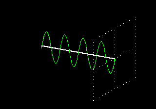
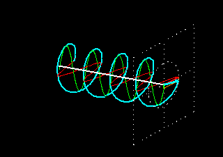
Linear polarization refers to the orientation of the electric field vector in an electromagnetic wave. In a linearly polarized wave, the electric field oscillates in a single plane, while the magnetic field oscillates perpendicular to it. The direction of polarization is determined by the direction of the electric field vector.
Types of Linear Polarization
Linear polarization can be further classified based on the orientation of the electric field relative to the Earth’s surface:
- Vertically polarized (linear): The electric field is perpendicular to the Earth’s surface. An example is the “whip” antenna on an automobile or the broadcast towers used for AM radio.
- Horizontally polarized (linear): The electric field is parallel to the Earth’s surface. A familiar example is television transmissions in the USA, which typically use horizontal polarization.
Understanding these distinctions is crucial, as the orientation of the electric field affects how well the transmitted signal propagates and interacts with its environment. Linear polarization can be achieved by passing unpolarized light through a polarizing filter or by using certain types of antennas.
Why is Horizontal Polarization Used for Television Broadcasting in the USA?
Horizontal polarization is the standard for television broadcasting across the United States, and for good reason. This orientation was selected not just out of technical tradition, but due to some practical advantages.
First, horizontal polarization helps minimize interference from vertically polarized signals, such as those used by mobile radios and other communication services. Since the majority of manmade radio noise—think power lines, vehicle ignitions, and other sources—is vertically polarized, choosing horizontal polarization for TV broadcasts provides a layer of protection against this type of interference. In short, the signal stays cleaner, and viewers get a more reliable picture.
Additionally, by separating the dominant polarizations for different services (horizontal for TV, vertical for mobile communications), industries can coexist with less cross-talk and overlap, making for a more efficient use of the radio spectrum.
Advantages of Linear Polarization
1. Longer read range: Linear polarization typically provides a longer read range compared to circular polarization. This is because the energy of the RF signal is concentrated in a single direction, allowing for greater distance between the reader and the tag.
2. Better penetration: Linear polarization is better at penetrating certain materials, such as liquids and metals. This makes it suitable for applications where tags may be placed on or near these materials.
3. Lower cost: Linear polarization antennas are generally less expensive to manufacture compared to circular polarization antennas.This is largely because achieving true circular polarization is technically more challenging—requiring more complex antenna designs, such as the helix antenna, which can drive up both material and production costs. As a result, linear polarization is often the preferred choice in budget-sensitive projects or when deployment at scale is necessary
Application Scenarios for Linear Polarization
1. Long-range applications: Linear polarization is ideal for applications where longer read ranges are required, such as in large warehouses or outdoor environments.
2. Applications with metal or liquid interference: Linear polarization can better penetrate metal or liquid interference, making it suitable for applications in which tags are attached to or near these materials.
3. Cost-sensitive applications: If cost is a major concern, linear polarization may be the better choice due to the lower cost of linear polarization antennas.
Why Is Vertical Polarization Commonly Used for Mobile and Two-Way Communications?
Vertical polarization is widely adopted in mobile and two-way communication systems because it offers consistent signal coverage in all directions. This omnidirectional performance is especially beneficial for environments where users frequently move—such as drivers on highways, taxi fleets in city streets, or handheld radios shifting location. Unlike horizontal polarization, which can be affected by buildings or terrain, vertically polarized signals are less susceptible to obstructions like hills or vehicles that are often encountered in suburban and rural settings.
Additionally, most mobile antennas—like those you see on cars or handheld radios—are designed with vertical polarization in mind, ensuring optimum compatibility and signal clarity. As a result, for applications above 30 MHz, vertical polarization has become the standard choice, delivering reliable communication where flexibility and broad coverage are required.
What is Circular Polarization?
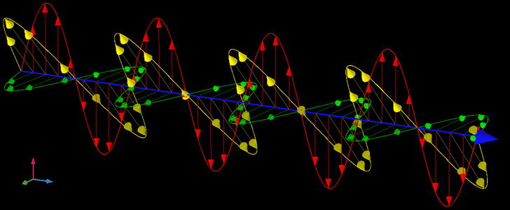
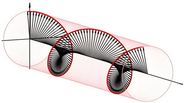
Circular polarization is a property of electromagnetic waves, such as light, where the direction of the electric field vector rotates in a circular pattern as the wave propagates. In circularly polarized light, the electric field vector traces out a helix or spiral shape in space. This is in contrast to linear polarization, where the electric field oscillates in a straight line, and elliptical polarization, where the electric field traces out an ellipse. Circular polarization can be either right-handed or left-handed, depending on the direction of rotation of the electric field vector.
Understanding Axial Ratio (Ellipticity) in Circular Polarization
In the context of circular polarization, the term axial ratio—also known as ellipticity—describes how perfectly circular the polarization of an electromagnetic wave is. To visualize this, imagine the electric field vector rotating as the wave moves forward, ideally tracing out a perfect circle. However, in real-world conditions, this path can become slightly oval-shaped (elliptical) instead of perfectly round.
The axial ratio measures the difference between the maximum and minimum strengths of the electric field as the antenna is rotated through all possible angles. This value is typically expressed in decibels (dB). A lower axial ratio—close to 0 dB—indicates nearly ideal circular polarization, meaning the wave maintains the same intensity in every direction. As the ratio increases above 1-2 dB, the polarization shifts toward elliptical, where the strength of the electric field varies more with orientation.
A well-designed circularly polarized antenna aims for an axial ratio as close to 0 dB as possible to ensure consistent performance, regardless of the tag or device angle.
Determining the Sense of Circular Polarization
The sense of circular polarization refers to the direction in which the electric field rotates as the electromagnetic wave travels. If you imagine looking straight into the approaching wave, right-hand circular polarization (RHC) is when the electric field appears to rotate clockwise, while left-hand circular polarization (LHC) rotates counterclockwise.
This distinction is important for matching antennas and ensuring optimal signal transmission and reception, as many RFID and communication systems specifically require either right-handed or left-handed circular polarization depending on their design.
Creating Elliptical Polarization with Crossed Yagi Antennas
Elliptical polarization, which is closely related to circular polarization, can be achieved using a clever setup with crossed Yagi antennas. This process involves taking two identical linearly polarized Yagi antennas and mounting them at right angles to each other—essentially, one is positioned horizontally while the other is vertically aligned.
To generate elliptical polarization, both Yagis need to be fed equal amounts of power, but here’s the key: their signals must also be 90 degrees out of phase. This is typically accomplished with a phasing network. When configured correctly, this arrangement creates an electromagnetic field where the electric vector traces out an ellipse as the wave moves through space. The quality of this elliptical polarization is described by its axial ratio, and well-constructed crossed Yagi systems generally achieve values in the range of ±1 to 3 dB.
For specialized applications, this crossed Yagi setup can be adapted further. By integrating a relay system, the antenna can be switched between right-hand and left-hand circular (or elliptical) polarization, offering flexibility for various operational requirements.
Advantages of Circular Polarization
1. Better tag orientation: Circular polarization is less affected by the orientation of the tag. This means that tags can be read from any angle, making it easier to achieve consistent and reliable reads.
2. Multiple tag reading: Circular polarization allows for the simultaneous reading of multiple tags, even if they are in different orientations. This makes it ideal for applications where multiple tags need to be read quickly and efficiently.
3. Improved performance in multi-path environments: Circular polarization is less affected by multi-path interference, where signals bounce off objects and create interference. This makes it suitable for applications in environments with many reflective surfaces.
Application Scenarios for Circular Polarization
1. Applications with multiple tags: Circular polarization is ideal for applications where multiple tags need to be read simultaneously, such as in retail inventory management or race timing systems.
2. Applications with varying tag orientations: Circular polarization is suitable for applications where tags can be in different orientations, such as when attached to moving objects or when tags are randomly placed.
3. Applications with multi-path interference: Circular polarization is better suited for environments with many reflective surfaces, such as warehouses with metal shelving or indoor environments with lots of walls and objects.

Why is Circular Polarization Often Used in Satellite Communications?
Circular polarization plays a crucial role in satellite communications, and for some pretty practical reasons. As radio waves travel between Earth and orbiting satellites, they encounter various atmospheric challenges—think of things like the Earth’s ionosphere or sudden changes in satellite position relative to the ground station. These factors can cause linearly polarized signals to twist and turn, sometimes enough to degrade the signal or even block it altogether.
Circular polarization sidesteps these issues by maintaining a consistent signal, regardless of changes in orientation or the effects of atmospheric phenomena like Faraday rotation. Whether a satellite is moving across the sky or the signal gets spun around by the upper atmosphere, circular polarization ensures reliable communication. This makes it a go-to choice for everything from TV satellites to global communication networks, where keeping the signal locked in is non-negotiable.
Why is circular polarization better than linear polarization for the RFID antenna?
Circular polarization is better than linear polarization for RFID antennas for several reasons:
1. Reduced cross-polarization interference: Circular polarization allows the RFID antenna to receive signals from any polarization orientation. This means that even if the RFID tag is oriented at a different angle, the circularly polarized antenna can still receive the signal effectively. In contrast, linearly polarized antennas require the RFID tag to be oriented in the same direction for maximum signal strength. Circular polarization reduces the chances of signal loss due to mismatched polarization between the antenna and the tag.
In addition, it’s important to note that while linearly polarized and circularly polarized antennas can technically communicate with each other, there is a trade-off involved. When a linearly polarized antenna interacts with a circularly polarized antenna (and vice versa), there can be up to a 3 dB loss in signal strength. In situations where signal levels are already weak, this loss can have a significant impact on communication reliability. By using circularly polarized antennas for both reader and tag, you help ensure optimal signal transfer and minimize the risk of communication issues due to polarization mismatch.
2. No need for directional awareness: With linear polarization, the orientation of the RFID tag is critical for successful scanning. If the tag is not aligned with the linearly polarized antenna, the signal strength decreases significantly. This requires users to be aware of the orientation of the RFID tag during scanning, which can be challenging in real-world scenarios. Circular polarization eliminates the need for directional awareness as it can receive signals from any orientation, providing more flexibility and ease of use.
3. Better performance in multi-path environments: Circular polarization is less affected by multi-path interference, which occurs when the RFID signal reflects off nearby objects and creates multiple signal paths. Linear polarization antennas are more susceptible to multi-path interference because the reflected signals may have different polarization orientations. Circular polarization helps mitigate this issue by receiving signals from all polarization angles, reducing the impact of multi-path interference.
4. Improved read range and coverage: Circular polarization provides a larger read range compared to linear polarization. The ability to receive signals from any polarization orientation allows the antenna to capture more energy from the RFID tag, resulting in a stronger and more reliable signal. This improves the read range and coverage area of the RFID system, allowing for faster and more accurate scanning of tags.
Overall, circular polarization offers significant advantages over linear polarization for RFID antennas, including reduced cross-pol interference, the elimination of directional awareness, better performance in multipath environments, and improved read range and coverage. These benefits make circular polarization a preferred choice for RFID applications.
Antennas with Switchable Polarization
It’s a great question—can antennas really switch between different polarizations, like linear, elliptical, and circular, on demand? The short answer is yes, thanks to some clever engineering.
There are specialized antennas designed with this flexibility in mind. These antennas, often referred to as polarization-agile or reconfigurable antennas, allow you to electronically change their polarization state. By using elements like PIN diodes, RF switches, or phase shifters in their feed networks, these antennas can toggle between linear, circular, and sometimes even elliptical polarizations at the push of a button (or a digital signal).
A few well-known examples include patch antennas with switchable feed points, as well as certain phased array antennas. Researchers and companies like Antenova and L3Harris have developed prototypes and commercial models suited for applications where dynamic polarization is advantageous—for instance, to adapt to rapidly changing tag orientations or to overcome unique environmental challenges.
Of course, there’s a trade-off: these systems add a layer of complexity, may cost more, and can draw more power than fixed-polarization cousins. But in scenarios where versatility and adaptability are paramount, antennas that can switch polarization offer a compelling solution.
Optimizing Communication Links Through Polarization Testing
When establishing a reliable communication link—whether for RFID, Wi-Fi, or amateur radio—it’s smart to experiment with both vertical and horizontal polarizations during setup. Each polarization behaves differently depending on the environment. For instance, in areas cluttered with metal structures, concrete walls, or tall shelving, one polarization might deliver a noticeably cleaner signal than the other.
Testing both polarizations can reveal which orientation minimizes interference from reflected signals or neighboring devices. If your environment is saturated with signals using a particular polarization, switching to the opposite orientation can provide natural isolation, helping your system avoid crosstalk and signal collision.
By spending a few minutes on this step, you can ensure your communication link operates at peak performance with less noise and more dependable connectivity—crucial whether you’re tracking inventory, timing a marathon, or simply maximizing the uptime of your wireless setup.
How Polarization Diversity Works in Modern Mobile and Cellular Communications
Polarization diversity has become increasingly important in today’s world of mobile radios and cellular phones. Since people often hold their devices at different angles—sometimes upright, sometimes sideways—the orientation, or polarization, of the antennas in these devices can vary unpredictably.
To address this challenge, modern communication systems use polarization diversity at the base station. Here’s how it works:
- Use of Multiple Polarizations: Base stations are equipped with antennas that emit and receive signals in different polarization orientations, such as vertical and horizontal or even circular polarization.
- Collocated Antennas: Thanks to advances in antenna design, these differently polarized antennas can now occupy the same physical location (collocated) as long as they are set at right angles (orthogonal) to each other and are well isolated. This minimizes interference between them.
- Improved Signal Reliability: With polarization diversity, the base station can receive signals effectively no matter how a user holds their device. This means fewer dropped calls and more consistent data speeds, even in busy environments like stadiums, airports, or city centers.
- Better Performance in Dynamic Environments: Polarization diversity makes the system more robust against multi-path interference—when signals bounce off buildings or other objects—because it can pick up the strongest signal available from any polarization.
By leveraging polarization diversity, mobile networks ensure reliable communication despite the random orientation of users’ devices, making everyday connectivity more seamless and robust.
Can Diversity Antennas Be Collocated if They Are Orthogonally Polarized?
In today’s world filled with handheld radios and mobile phones, devices are often used in unpredictable orientations. This randomness has highlighted the benefits of polarization diversity—using multiple antennas with different polarization angles to improve signal reliability.
A key finding in this area is that diversity antennas don’t always need to be spaced apart physically to reduce interference between them. When two antennas are polarized at right angles—orthogonal to each other—and are properly isolated, they can actually be mounted together in the same location. Companies like Ericsson and Nokia have demonstrated that collocated, orthogonally polarized antennas can reliably achieve signal diversity, helping maintain strong connections even as device orientation changes.
This approach allows for more compact antenna installations, such as at cellular base stations, while still gaining the benefits of polarization diversity to handle a wide range of device positions and environments.
What is Diversity Reception and How Does It Combat Signal Fading?
Now that we’ve compared circular and linear polarization, it’s worth touching on another clever trick used to maintain strong, reliable RFID signals—diversity reception.
Signal fading is a common hitch in wireless systems. It comes in two flavors:
- Long-term fading: Caused by larger changes in the environment, like shifting weather conditions or when a receiver moves behind obstructions such as buildings or hills.
- Short-term fading (multipath fading): Happens when signals bounce off nearby objects (walls, shelves, you name it), creating multiple, overlapping paths to the receiver. This can weaken or even cancel out the main signal, especially indoors or in cluttered areas.
Diversity reception is a technique to tackle these issues. In a typical diversity setup, two or more antennas (sometimes paired with separate receivers) are used at the same location but positioned or oriented differently. This increases the likelihood that, even if one antenna suffers from signal fading due to reflection or obstruction, another will pick up a stronger, clearer version of the signal. The system then selects, or “votes for,” the best available signal for processing—sort of like having backup players ready to take over when one stumbles.
One traditional method involves spacing the antennas quite far apart (20 wavelengths or more—about 20 to 25 feet at 880 MHz, for example), which isn’t always practical for most facilities.
Fortunately, there’s a more space-efficient version called polarization diversity. Instead of separating antennas by distance, they’re positioned with different polarizations—for example, one vertical, one horizontal, or even circularly polarized—while staying close together. This setup greatly improves the odds that at least one antenna is well-matched to the polarization of an incoming signal, which is especially valuable when dealing with the unpredictable orientation of devices like cell phones or handheld scanners.
So, diversity reception—especially with polarization diversity—helps keep RFID and other wireless systems robust, even in challenging environments where signal strength might otherwise dip or “fade” unpredictably.
Evolution of FM Radio Polarization for Cars
A quick trip back in time reveals an interesting twist in the story of FM radio. In its infancy—think the heyday of classic cars and soda fountains—FM radio transmissions were primarily broadcast using horizontal polarization. This made perfect sense: home radio receivers typically sported horizontal antennas, and everything hummed along smoothly.
But then came the rise of the automobile and its ever-present vertical whip antenna. Suddenly, millions of car radios weren’t picking up signals as well as their living room-bound cousins. The orientation mismatch meant less-than-stellar radio reception for drivers hoping to catch the latest Beatles tune on their way to the drive-in.
To fix this, regulators—specifically the FCC in the United States—stepped in during the 1960s. They updated the rules to permit FM stations to transmit using right-hand circular (RHC) or elliptical polarization. This allowed broadcasts to reach both horizontal and vertical antennas effectively, vastly improving FM reception in vehicles without compromising home listening. In short, a simple tweak to the way signals were sent helped everyone, from the couch potato to the road-tripper, enjoy clearer music and news wherever their day took them.
Key Considerations When Installing Antennas Near Other Antennas
When installing your RFID antenna on a tower or building alongside other antennas, it’s important to be strategic about placement. Antennas that are too close to each other can introduce unwanted interference, such as desensitization, which can degrade performance.
To minimize these issues, try the following:
- Maximize distance: Even adding a few extra feet of separation—especially in the UHF range—can significantly reduce interference and improve overall reliability.
- Assess positioning: If possible, stagger antennas vertically or horizontally, rather than clustering them in one area.
- Survey your surroundings: Take note of nearby metal structures or reflective surfaces, as these can compound interference in crowded antenna environments.
Taking these steps will help you achieve optimal performance and ensure that your RFID system runs smoothly, even when space is tight or multiple antennas are in play.
Summary
In summary, a linear polarization RFID antenna offers longer read ranges, better penetration of certain materials, and lower cost. It is suitable for long-range applications, applications with metal or liquid interference, and cost-sensitive applications.
On the other hand, a circular polarization RFID antenna offers better tag orientation, the ability to read multiple tags simultaneously, and improved performance in multipath environments. It is suitable for applications with multiple tags, varying tag orientations, and environments with multi-path interference.
By considering the advantages and application scenarios of each, you can make an informed decision about which type of polarization is best for your RFID system requirements.