 Skip to content
Phased array antennas have revolutionized antenna technology, offering precise control over the direction and intensity of radio waves. They are used in a wide range of industries, from telecommunications to defense, due to their advanced capabilities. This article provides an overview of phased array antennas, including their structure, how they work, where they are used, and what the future holds for this technology.
What is a Phased Array Antenna? A phased array antenna is a type of antenna that uses multiple individual antennas (elements) to form a single, directional antenna capable of steering its beam electronically without moving the antenna physically. This capability allows for more precise control over the direction and strength of the signal, making it ideal for applications requiring high levels of accuracy and flexibility.
Now, let’s delve deeper into the various aspects of phased array antennas to understand their functionality and benefits.
What are Phased Array Antennas Used For?
Phased array antennas are indeed versatile and find applications across various fields due to their ability to electronically steer the beam direction without physically moving the antenna. Here are some detailed uses:
1. Radar Systems:

– Military Radar: Used for tracking and targeting enemy aircraft, missiles, and other threats. They provide rapid beam steering and high-resolution imaging.
– Weather Radar: Used to detect and predict weather patterns, including precipitation, storm movements, and wind speeds.
2. Satellite Communications:

– Ground Stations: Phased array antennas enable ground stations to maintain continuous communication with satellites, even as they move across the sky.
– Satellite Onboard Antennas: Used for beamforming to focus signals on specific areas on Earth, improving communication quality and efficiency.
3. Wireless Networks:
– 5G Networks: Essential for massive MIMO (Multiple Input Multiple Output) systems, phased array antennas help in beamforming to enhance signal strength and coverage, reduce interference, and increase data rates.

– Wi-Fi: Used in advanced Wi-Fi systems to improve signal directionality and coverage within buildings and complex environments.
4. Aviation:

– Air Traffic Control: Ensures precise tracking of aircraft positions and movements, enhancing safety and efficiency in airspace management.
– Aircraft Navigation: Helps in navigation and collision avoidance systems, providing accurate positional data.
5. Telecommunications:
– Cell Towers: Used to dynamically adjust coverage areas and improve signal quality, especially in densely populated urban areas.
– Broadcasting: Enhances the quality and reach of broadcast signals for television and radio.
6. Medical Imaging:
– MRI and Ultrasound: Phased array antennas are used in medical imaging devices to focus and steer signals, improving image resolution and diagnostic capabilities.
7. Astronomy:
– Radio Telescopes: Used in large radio telescope arrays to study celestial phenomena by steering the observation beam electronically.
8. Automotive:
– Advanced Driver-Assistance Systems (ADAS): Phased array radar systems are used in vehicles for adaptive cruise control, collision avoidance, and autonomous driving features.
9. Maritime:

– Ship Navigation and Communication: Ensures reliable communication and navigation for ships, even in challenging sea conditions.
The flexibility, speed, and precision of phased array antennas make them indispensable in these and many other applications, driving advancements in technology and improving operational efficiencies across various sectors.
What are the Benefits of Phased Array Antennas?
1. Beam Steering:
– Electronic Steering: Phased array antennas can electronically steer the direction of their beam without physically moving the antenna. This allows for rapid and precise control of the beam direction.
– Agility: The ability to quickly change the beam direction makes phased array antennas ideal for applications requiring dynamic tracking, such as radar and satellite communications.
2. Increased Reliability:
– No Moving Parts: Since beam steering is accomplished electronically, phased array antennas have fewer mechanical parts that can wear out or fail, leading to higher reliability and lower maintenance costs.
3. Enhanced Performance:
– High Gain: Phased array antennas can achieve high gain by combining the signals from multiple elements, which improves signal strength and quality.
– Reduced Interference: By shaping and directing the beam precisely, phased array antennas can minimize interference from unwanted directions.
4. Flexibility in Design:
– Scalability: Phased array systems can be scaled to different sizes and configurations, making them suitable for a wide range of applications, from small handheld devices to large radar systems.
– Multi-functionality: A single phased array antenna can be used for multiple functions, such as communication, radar, and electronic warfare, by dynamically adjusting the beam patterns.
5. Improved Signal Quality:
– Adaptive Beamforming: Phased array antennas can adapt their beam patterns in real-time to optimize signal reception and transmission, even in challenging environments.
– Spatial Filtering: The ability to focus the beam in specific directions helps in filtering out noise and improving the signal-to-noise ratio.
6. Compact and Lightweight:
– Integration: Phased array antennas can be integrated into the surfaces of vehicles, aircraft, and other structures, reducing the need for bulky and protruding antenna structures.
– Portability: The compact size and lightweight nature of phased array antennas make them suitable for portable and mobile applications.
7. Enhanced Security:
– Low Probability of Intercept: The ability to rapidly change beam directions and patterns can make it harder for adversaries to detect and intercept the signals, enhancing communication security.
8. Cost-Effectiveness:
– Long-Term Savings: While the initial cost of phased array antennas may be higher, the long-term savings in maintenance, reliability, and versatility can make them more cost-effective over time.
These benefits make phased array antennas highly suitable for a wide range of applications, including military, aerospace, telecommunications, and commercial sectors.
How Does a Phased Array Antenna Work?
A phased array antenna works by adjusting the phase of the signal at each individual antenna element. By changing the phase, the combined signal from all elements can be directed in a specific direction. This electronic steering is achieved through a combination of phase shifters, amplifiers, and control systems.
Basic Principle
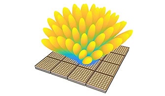
A phased array antenna is composed of multiple individual antenna elements arranged in a specific geometric pattern, such as a linear or planar array. The key to its operation is the ability to control the phase of the signal transmitted or received by each element. By adjusting these phases, the antenna can steer the direction of the main beam of radiation without physically moving the antenna.
Array Topologies
Phased array systems are often classified by how their antenna elements are positioned, which in turn determines how the beam can be steered:
- Line (1D) Arrays: Here, the elements are arranged in a straight line—either horizontally to steer the beam in azimuth, or vertically to adjust elevation.
- Planar (2D) Arrays: The elements are laid out on a flat surface, allowing for two-dimensional steering in both azimuth and elevation. This enables coverage of the full space above the antenna.
- 3D Arrays: For applications requiring even greater flexibility, elements can be distributed throughout a volume, permitting the beam to be directed virtually anywhere in three-dimensional space.
This variety of configurations allows phased arrays to be tailored for different applications, from radar and satellite communications to automotive sensors and wireless networks, all while maintaining the core advantage of electronic beam steering.
Understanding Azimuth and Elevation
When discussing the direction of a phased array antenna’s beam, two key terms often come up: azimuth and elevation. These coordinates help pinpoint exactly where the main lobe of the antenna is aimed.
- Azimuth refers to the angle along the horizontal plane—think of it as pointing a flashlight around in a circle while keeping it flat on the ground. This angle is measured clockwise from a reference direction, usually true north.
- Elevation is the angle above the horizon—imagine tilting that flashlight up toward the sky. A higher elevation means a steeper upward angle.
Together, azimuth and elevation allow precise control and description of where the antenna’s maximum signal strength is focused, making them fundamental in applications like radar tracking, satellite communications, and wireless networks.
Components

1. Antenna Elements: These are the individual radiating or receiving units that make up the array. They can be dipoles, patches, or other types of antennas.
2. Phase Shifters: These are devices that adjust the phase of the signal at each antenna element. By changing the phase, the signals from different elements can constructively or destructively interfere, effectively steering the beam in the desired direction.
3. Amplifiers: These are used to boost the signal strength as needed, ensuring that the transmitted or received signal maintains adequate power levels.
4. Control System: This system manages the phase shifters and, in some cases, the amplifiers. It can be controlled by software that calculates the required phase shifts to steer the beam in a particular direction.
Working Mechanism
1. Transmission:
– A signal is fed into the array.
– The control system calculates the required phase shifts for each element to steer the beam in the desired direction.
– Phase shifters adjust the phase of the signal at each element.
– The signals from all elements combine in free space, and due to constructive and destructive interference, the main beam is directed in the desired direction.
2. Reception:
– Incoming signals are received by the antenna elements.
– The control system adjusts the phase of the received signals to steer the reception beam in the desired direction.
– The adjusted signals are combined, amplifying the signal from the desired direction and suppressing signals from other directions.
Beam Steering
The direction of the beam can be changed almost instantaneously by adjusting the phase shifts electronically. This allows for rapid scanning of different directions, which is particularly useful in applications like radar, where the ability to quickly change the direction of the beam is crucial.
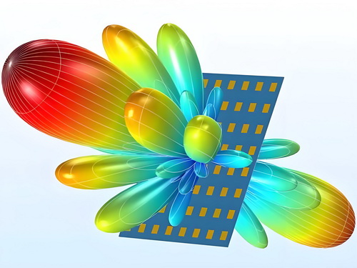
What Are Sidelobes in Phased Array Antennas and Why Do They Matter?
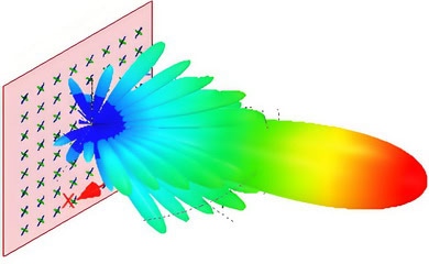
When discussing phased array antennas, it’s essential to understand the concept of sidelobes. In a radiation pattern, the primary lobe—or main beam—is focused in the desired direction, carrying most of the transmitted or received energy. However, there are also secondary areas of radiation known as sidelobes. These are smaller “bumps” or peaks found outside the main beam.
Sidelobes are significant because they represent energy that is radiated away from the intended direction. This can lead to several issues:
- Wasted Energy: Energy directed into sidelobes does not contribute to the primary task, reducing overall antenna efficiency.
- Potential Interference: Sidelobes can inadvertently pick up or transmit signals in undesired directions, which may result in interference with other systems or unwanted detection in sensitive applications.
- Security Concerns: In military or secure communications, strong sidelobes can leak signals to unintended listeners, compromising confidentiality.
For these reasons, antenna designers aim to minimize sidelobe levels through careful array design and signal processing techniques. By reducing sidelobes, phased array antennas can provide more precise, efficient, and secure operation for applications ranging from weather radar to 5G base stations.
What is Beam Width, and How is it Measured?
When discussing phased array antennas, you’ll often hear about “beam width.” Simply put, beam width describes how wide the main lobe—or strongest part—of the radiated energy is, usually stated in degrees. It’s a key parameter that defines the antenna’s directional focus and its ability to distinguish between different signals in various directions.
There are two common methods for measuring beam width:
- First Null Beam Width (FNBW): This measurement refers to the angular distance between the first points on either side of the main lobe where the signal strength drops to zero (the so-called “nulls”). Essentially, it tells you how wide the main lobe appears before the signal significantly falls off.
- Half-Power Beam Width (HPBW): Rather than looking for the points where the signal vanishes, this measure finds where the power falls to half its maximum value (or -3 dB down from the peak). The angular span between these points is the HPBW, and it’s frequently used because it captures the width where the antenna is most effective.
Understanding both FNBW and HPBW helps engineers and system designers evaluate how precisely an antenna can focus its energy—crucial for applications requiring high resolution or where interference from adjacent directions is a concern.
How Do Engineers Use Simulation to Evaluate and Improve Phased Array Antenna Performance?
Simulation plays a vital role in the design and optimization of phased array antennas, especially given the increasing complexity of modern systems with hundreds or thousands of antenna elements. Manually calculating factors such as element spacing, constructive and destructive interference, and sidelobe behavior would be extraordinarily tedious—if not outright impossible—for most real-world arrays. Moreover, physically measuring radiation patterns in specialized environments can be costly and resource-intensive.
Streamlining the Design Process
With simulation software, engineers can:
- Model the behavior of entire antenna arrays and individual antenna elements.
- Design and refine the beamforming components for optimal signal direction and strength.
- Predict how the antenna will interact with the larger system, from circuit-level effects to full electromagnetic environments.
Simulation tools allow for the quick identification and adjustment of design parameters, enabling engineers to achieve the desired performance with greater efficiency and fewer prototypes.
Accounting for Real-World Variations
Another advantage of simulation is the ability to anticipate the effects of manufacturing tolerances and material inconsistencies on antenna performance. Engineers can tweak design parameters virtually to evaluate robustness and consistency, long before the first physical prototype is produced.
Modeling Installation and Environmental Impacts
Advanced simulation methods also allow teams to assess how antennas perform in their final environment—whether mounted on towers, vehicles, or aircraft. By simulating electromagnetic waves as they interact with nearby structures, terrain, or even cityscapes, engineers can predict and mitigate issues such as signal distortion or self-coupling. Technologies like ray-tracing enable detailed analysis of signal paths through complex environments, whether it’s navigating urban canyons or bouncing around inside warehouses.
Beyond Electromagnetics: Thermal and Structural Considerations
Once the electromagnetic performance is tuned, design teams often turn to simulation for thermal management and structural analysis. Simulating heat dissipation and mechanical stresses helps ensure that the antenna array can operate reliably under varying temperatures and mechanical loads. For applications involving vehicles or aircraft, fluid dynamics simulations can further inform design decisions by modeling aerodynamic forces encountered at high speed.
By leveraging a suite of simulation tools, engineers can comprehensively evaluate and improve phased array antenna designs, ensuring high performance, reliability, and cost-effectiveness from the earliest design phases through to deployment.
How Does Simulation Assist in the Design and Optimization of Phased Array Antennas?
Simulation is a vital tool that streamlines the design and optimization process for phased array antennas—especially as array sizes and system complexity grow. Manually calculating factors like array spacing, beam patterns, and sidelobe levels can quickly become impractical, even for modestly sized arrays. Additionally, physically measuring antenna radiation patterns in specialized environments, such as anechoic chambers, is both time-consuming and costly.
Efficient Design and Verification
With modern electromagnetic simulation software, engineers can virtually construct and test antenna arrays and their individual components before ever building physical prototypes. By modeling both the antenna elements and the intricate beamforming circuits, they can predict how the array will behave, optimize its performance, and troubleshoot potential issues early. This virtual approach saves time, reduces development costs, and allows for more rapid iterations.
Optimization and System Interaction
One major advantage of simulation is the ability to experiment with different design parameters—such as element arrangement, phase shift strategies, and feed networks—to find the optimal configuration for specific requirements. Teams can also examine the influence of manufacturing tolerances, material properties, and environmental factors on performance. Importantly, simulation isn’t limited to isolated antennas; it can also model how antennas interact with other parts of the system, nearby structures, and even complex real-world environments.
Advanced Modeling Capabilities
State-of-the-art simulation platforms include advanced features for studying long-range propagation and the effects of obstacles—whether that’s warehouse shelving or city buildings—on signal strength and quality. These tools help engineers predict how the antenna will perform in its intended environment, so they can account for reflections, blockages, or interference that might degrade performance.
Thermal and Mechanical Considerations
Once the electromagnetic aspects are refined, simulation helps assess how the antenna system copes with mechanical stress, vibration, and thermal loads—critical for installations in mobile or outdoor environments. Structural and thermal simulations ensure the design is robust enough to withstand real-world operating conditions, whether the antenna is mounted on a stationary tower or a fast-moving vehicle.
Summary
By leveraging simulation, engineers accelerate the phased array antenna development cycle—from concept and optimization to environmental validation—ensuring reliable performance, reduced costs, and greater confidence in the final design.
What are the Disadvantages of Phased Array Antennas?
Phased array antennas offer numerous advantages, such as electronic beam steering, high reliability, and rapid response times. However, they also come with several disadvantages:
1. Complexity: Phased array systems are complex in terms of design, manufacturing, and maintenance. The complexity increases with the number of elements in the array, requiring sophisticated control algorithms and signal processing.
2. Cost: The development and production of phased array antennas are generally more expensive than traditional antennas. The high cost is due to the advanced materials, intricate manufacturing processes, and the need for high-precision components.
3. Power Consumption: Phased array antennas can consume significant amounts of power, especially in active arrays where each element has its own transmitter and receiver. This can be a limitation for battery-operated or energy-constrained systems.
4. Thermal Management: The high power consumption can lead to significant heat generation, requiring effective thermal management solutions. This adds to the complexity and cost of the system.
5. Bandwidth Limitations: While phased arrays offer excellent beam steering capabilities, their performance can be limited by bandwidth constraints. Designing a wideband phased array that maintains performance across a broad frequency range can be challenging.
6. Grating Lobes: At higher frequencies or with wider beam steering angles, phased arrays can produce grating lobes—undesirable secondary lobes that can interfere with the main signal. This requires careful design to mitigate.
7. Calibration and Alignment: Ensuring that all elements in a phased array are properly calibrated and aligned is crucial for optimal performance. Misalignment can degrade the antenna’s performance and require frequent recalibration.
8. Size and Weight: While phased arrays can be made compact, larger arrays required for higher gain can still be bulky and heavy, posing challenges for certain applications like small satellites or portable systems.
9. Signal Integrity: The intricate signal processing required for beamforming and steering can introduce delays and distortions, which need to be carefully managed to maintain signal integrity.
10. Limited Scan Angle: The effective beam steering angle is typically limited to less than ±60 degrees from the array normal. Beyond this range, the antenna performance degrades significantly.
11. Environmental Sensitivity: Phased array antennas can be sensitive to environmental factors such as temperature variations, which can affect the phase and amplitude characteristics of the elements, thus impacting overall performance.
12. Maintenance and Repair: Due to their complexity, phased array systems can be more challenging to maintain and repair compared to traditional antennas. Faulty elements can degrade the performance of the entire array, necessitating specialized diagnostic and repair procedures.
Understanding these disadvantages is crucial for engineers and designers to make informed decisions about when and how to use phased array antennas effectively.
Challenges of Designing Phased Array Antennas Without Simulation
Designing phased array antennas by relying solely on traditional, manual methods presents a unique set of hurdles for engineers, particularly as array size scales up. Here’s why simulation tools have become indispensable in the field:
- Complex Calculations: Without simulation, engineers must calculate element spacing, beam patterns, and sidelobe characteristics by hand. This task grows exponentially more difficult as arrays expand from a handful of elements to thousands, making manual optimization nearly impossible.
- Pattern Prediction: Accurately predicting the overall radiation pattern of the array requires meticulous mathematical work, factoring in intricate interactions among all elements. A small calculation error can lead to significant flaws in the final design.
- Labor-Intensive Testing: Physical measurements of antenna performance, such as radiation patterns, typically require access to anechoic chambers—specialized environments that mimic free space, like those used by NASA or the FCC. These tests are not only costly but also extremely time-consuming. Each round of prototyping and measurement can delay projects and inflate budgets.
- Sidelobe Management: Managing unwanted sidelobes—and ensuring the main beam maintains its intended direction and strength—demands iterative adjustments that are challenging to perfect without the feedback loop that simulation provides.
- Error Detection and Troubleshooting: Identifying the causes behind unexpected behaviors or performance drops becomes a drawn-out process, as engineers must investigate each element and interaction individually rather than running rapid diagnostics digitally.
In short, without simulation software from platforms like CST Studio Suite or HFSS, what might take minutes on a computer can consume weeks or months in manual calculation and laboratory testing. Embracing simulation accelerates development, enhances accuracy, and helps engineers navigate the many complexities of modern phased array design.
Phased Array Antennas Frequency
Phased array antennas are versatile and can indeed operate across a broad spectrum of frequencies, making them suitable for various applications. Here are some key points regarding the frequency ranges and their applications:
1. Low-Frequency Bands (3 kHz to 30 MHz)
– Applications: These frequencies are typically used for traditional radio communications, maritime communications, and some military applications.
– Characteristics: Longer wavelengths allow for better penetration through obstacles and long-distance communication with lower power requirements.
2. Medium-Frequency Bands (30 MHz to 300 MHz)
– Applications: Commonly used in VHF (Very High Frequency) radio communications, television broadcasting, and some aviation communications.
– Characteristics: These frequencies offer a good balance between range and data capacity, making them suitable for various communication needs.
3. High-Frequency Bands (300 MHz to 3 GHz)
– Applications: Includes UHF (Ultra High Frequency) bands used in TV broadcasting, mobile phones, Wi-Fi, and some radar systems.
– Characteristics: Higher data rates and better resolution for radar systems, but reduced range and penetration compared to lower frequencies.
4. Very High-Frequency Bands (3 GHz to 30 GHz)
– Applications: Used in modern radar systems, satellite communications, and some 5G cellular networks.
– Characteristics: These frequencies allow for high-resolution imaging and high data transmission rates, but are more susceptible to atmospheric attenuation and require line-of-sight communication.
5. Super High-Frequency and Extremely High-Frequency Bands (30 GHz to 300 GHz)
– Applications: Millimeter-wave radar, advanced satellite communications, and emerging 5G and 6G technologies.
– Characteristics: Very high data rates and resolution with significant challenges in terms of signal attenuation and range, often requiring advanced technologies like beamforming and multiple-input multiple-output (MIMO) systems.

Design Considerations
– Element Spacing: The spacing between antenna elements in a phased array is crucial and is typically a fraction of the wavelength of the operating frequency. This spacing affects the beamforming capabilities and the overall performance of the antenna.
– Beam Steering: Phased array antennas can electronically steer the direction of the beam without moving the antenna physically. This is achieved by adjusting the phase of the signal at each element.
– Bandwidth: The design of the antenna elements and the feed network determines the operational bandwidth. Wideband phased arrays can operate over a broad range of frequencies, making them versatile for multiple applications.
– Material and Manufacturing: The choice of materials and manufacturing techniques can affect the performance, especially at higher frequencies where precision is critical.
Phased array antennas are a cornerstone technology in modern communications and sensing systems, offering flexibility and performance across a wide range of frequencies.
Phased Array Antennas Polarization
Phased array antennas can be designed to have different polarizations, including linear polarization and circular polarization.
Linear polarization occurs when the electric field of the radio wave is oriented in a single plane. This can be either horizontal or vertical polarization, depending on the orientation of the electric field. Linearly polarized phased array antennas are commonly used in applications such as satellite communication, radar systems, and wireless communication.
Circular polarization occurs when the electric field of the radio wave rotates in a circular pattern as it propagates. This can be either right-hand circular polarization (RHCP) or left-hand circular polarization (LHCP), depending on the direction of rotation. Circularly polarized phased array antennas are used in applications such as satellite communication, GPS systems, and wireless communication.
The choice of polarization for a phased array antenna depends on the specific application and the requirements of the system. Factors such as the environment, interference, and the desired coverage area can influence the choice of polarization.
Phased Array Antennas Gain
Phased array antennas are a type of antenna array that can electronically steer the direction of the beam of radio waves. They consist of multiple individual antenna elements, each of which can be controlled in terms of phase and amplitude. This allows the array to form a directed beam of radio waves that can be steered without physically moving the antenna.
Gain of Phased Array Antennas
The gain of a phased array antenna is a measure of the antenna’s ability to direct radio frequency energy in a particular direction. It is typically expressed in decibels (dB) and is a critical parameter in determining the performance of the antenna system.
Before diving into the specifics for phased arrays, it’s helpful to understand the general concept of antenna gain. Antenna gain is the strength of the signal (the amplitude) in any given direction compared to a theoretical single isotropic radiator, which would spread the signal equally in all directions. The higher the gain, the more effectively the antenna focuses energy in a preferred direction, resulting in improved signal strength and range.
Factors Affecting Gain
1. Number of Elements: The gain of the phased array increases with the number of individual antenna elements. More elements can constructively interfere to form a stronger, more focused beam.
2. Element Spacing: The distance between individual antenna elements affects the array’s ability to form a coherent beam. Typically, elements are spaced about half a wavelength apart to avoid grating lobes and to maximize gain.
3. Element Pattern: The radiation pattern of each individual element also influences the overall array gain. Ideally, the elements should have a broad radiation pattern to allow for effective beam steering.
4. Aperture Size: The physical size of the antenna array, or its aperture, directly correlates with gain. A larger aperture can capture and direct more energy.
5. Efficiency: The efficiency of the individual elements and the overall array affects the gain. Losses due to impedance mismatches, material properties, and other factors can reduce the effective gain.
6. Beamforming Techniques: Advanced beamforming techniques can optimize the phase and amplitude of each element to maximize gain in the desired direction.
Calculating Gain
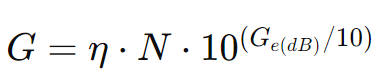
The gain ( G ) of a phased array antenna can be approximated by:
G=η⋅N⋅Ge
where:
- η is the efficiency of the antenna array.
- N is the number of elements in the array.
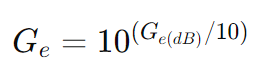
- Ge is the gain of a single element (in linear scale).
For a more realistic scenario where the elements have their own gain ( Ge ), the total gain becomes:
Example Calculation
Given:
- Number of elements, N=100
- Gain of a single element, Ge(dB)=2 dB
- Efficiency, η=0.9
1. Convert the gain of a single element to linear scale:
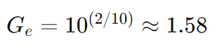
2.Calculate the total gain in linear scale:
G=0.9⋅100⋅1.58=142.2
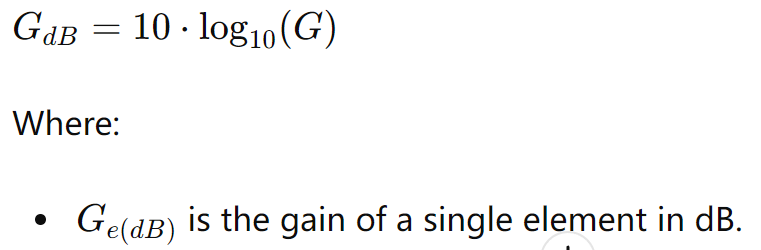
3.Convert the total gain back to dB:

Thus, the phased array antenna has a gain of approximately 21.5 dB.
Summary Formula
To calculate the gain GGG of a phased array antenna with given parameters:
And the final gain in dB:
Conclusion
Phased array antennas offer significant advantages in terms of beam steering and gain. Understanding the factors that influence gain and how to calculate it is essential for designing and optimizing these complex antenna systems.By comparing array gain to the benchmark of an isotropic radiator, engineers can better evaluate and improve antenna performance for a wide range of challenging applications.
Phased Array Antennas Types
Phased array antennas are versatile and widely used in various applications, from radar systems to telecommunications. Here are some common types of phased array antennas:
1. Active Phased Array (APA):

– Description: In an active phased array, each antenna element is equipped with its own individual amplifier. This allows for greater control and flexibility over the signal strength and phase of each element.
– Advantages: High efficiency, improved signal-to-noise ratio, and greater reliability due to redundancy.
– Applications: Military radar systems, satellite communications, and advanced wireless communications.
2. Passive Phased Array (PPA):
– Description: A passive phased array uses a central amplifier to drive all the antenna elements. The phase shifters are used to control the phase of the signal at each element.
– Advantages: Simpler design and lower cost compared to active phased arrays.
– Applications: Older radar systems, some commercial and industrial applications.
3. Electronically Scanned Array (ESA):
– Description: An electronically scanned array uses electronic methods to steer the beam without moving the antenna physically. This is achieved through phase shifters or time delay units that adjust the phase of the signal at each element.
– Advantages: Rapid beam steering, increased reliability due to fewer moving parts, and the ability to form multiple beams simultaneously.
– Applications: Modern radar systems, telecommunications, and electronic warfare.
4. Digital Beamforming Array:
– Description: In a digital beamforming array, the signals from each antenna element are digitized and processed using digital signal processing (DSP) techniques to form the desired beam pattern.
– Advantages: High precision in beamforming, flexibility in handling multiple beams, and advanced signal processing capabilities.
– Applications: Advanced radar systems, 5G communications, and satellite systems.
Additional Types and Configurations
While the above categories cover the fundamental approaches, several variations and hybrid systems are worth noting for their specialized capabilities:
- Passive Electronically Scanned Array (PESA): A classic configuration where a single transceiver drives the entire array, with phase shifting handled passively. This approach is commonly found in early phased array radar and remains in use for certain cost-sensitive or legacy applications.
- Active Electronically Scanned Array (AESA): Building on the active array concept, AESA equips each element (or small subarray) with its own analog transceiver module, allowing for dynamic phase and amplitude control. AESA antennas are favored in modern military applications for their agility, reliability, and electronic countermeasure resistance.
- Digital Beamforming (DBF) Phased Array: Here, each element’s signal is converted to digital and all beamforming occurs in the digital domain. This method enables the creation of multiple independent beams and pattern nulls using advanced hardware like FPGAs or dedicated array processors. DBF arrays can adapt their patterns in real time to minimize interference from known directions.
- Hybrid Beamforming Phased Array: Some systems combine analog and digital beamforming. Subarrays might use analog transceivers for initial phase control, while digital processing refines the pattern and enables complex functions such as clustering beams. This hybrid approach balances cost, complexity, and performance, making it popular in emerging high-capacity wireless systems.
Each configuration brings unique strengths to phased array design, allowing engineers to tailor antenna performance to the specific demands of radar, communications, remote sensing, and beyond. With advances in materials, processing speed, and miniaturization, the lines between these categories continue to blur—enabling phased arrays to fulfill ever more challenging roles in both civil and defense technology.
5. Conformal Phased Array:
– Description: Conformal phased arrays are designed to conform to the shape of the platform on which they are mounted, such as the fuselage of an aircraft or the hull of a ship.
– Advantages: Reduced aerodynamic drag, better integration with the platform, and the ability to cover a wide field of view.
– Applications: Military aircraft, naval vessels, and other platforms requiring stealth and low-profile antenna systems.
6. Adaptive Phased Array:
– Description: Adaptive phased arrays can dynamically adjust their beam patterns in response to changing environmental conditions or interference.
– Advantages: Improved performance in dynamic environments, enhanced interference mitigation, and better signal quality.
– Applications: Advanced radar systems, wireless communications, and electronic warfare.
7. Switched Beam Arrays:
– Description: Switched beam arrays use a finite number of fixed beam patterns and switch between them as needed. This is a simpler form of beam steering compared to fully electronic scanning.
– Advantages: Simpler design and lower cost compared to fully electronically scanned arrays.
– Applications: Some commercial communication systems and simpler radar systems.
Each type of phased array antenna has its own set of advantages and is suited to different applications based on requirements such as cost, complexity, performance, and specific use cases.
Phased Array Antennas Components
Phased array antennas are sophisticated systems that can electronically steer their beams without moving the antenna itself. They are composed of several key components, each playing a crucial role in the antenna’s performance. Here are the main components of phased array antennas:
1. Radiating Elements:
– These are the individual antenna elements that emit and receive electromagnetic waves. Common types include dipoles, patches, and slots.
2. Phase Shifters:
– These devices adjust the phase of the signal at each radiating element to steer the beam in the desired direction. Phase shifters can be analog or digital.
3. Beamforming Network:
– This network distributes the signal to the various radiating elements with the correct amplitude and phase. It can be implemented using various technologies, including corporate feed networks, series feed networks, and digital beamforming.
4. Power Dividers/Combiners:
– These components split the input signal into multiple paths for transmission or combine multiple received signals into a single path for reception.
5. Control System:
– A control system manages the phase shifters and other components to dynamically steer the beam. This system can be implemented using software, firmware, or hardware controllers.
6. RF Chains:
– Each radiating element typically has its own RF chain, which includes amplifiers, filters, and mixers to process the signal before transmission or after reception.
7. T/R Modules (Transmit/Receive Modules):
– These modules are integrated units that handle both transmission and reception functions for each radiating element. They include amplifiers, phase shifters, and sometimes frequency converters.
8. Digital Signal Processing (DSP):
– DSP units process the received signals, performing tasks such as beamforming, filtering, and demodulation. They also generate the signals for transmission.
9. Antenna Array Structure:
– This is the physical framework that holds the radiating elements in place. It ensures proper spacing and alignment of the elements to achieve the desired radiation pattern.
10. Cooling System:
– Phased array antennas, especially those with high power levels, generate significant heat. Cooling systems, such as heat sinks, fans, or liquid cooling, are used to maintain optimal operating temperatures.
11. Calibration and Monitoring System:
– These systems ensure the phased array operates correctly by continuously monitoring performance and making necessary adjustments. Calibration systems can compensate for manufacturing tolerances and environmental changes.
12. Power Supply:
– A stable and reliable power supply is crucial for the operation of all the electronic components in the phased array antenna.
Understanding these components and how they interact is essential for designing, building, and operating phased array antennas effectively.
Differences Between Phased Array Antennas and Traditional Antennas
Phased array antennas and traditional antennas serve the same fundamental purpose of transmitting and receiving electromagnetic waves, but they differ significantly in terms of design, functionality, and applications. Here are some key differences between the two:
Design and Structure
1. Traditional Antennas:
– Typically consist of a single element or a simple array of elements.

– Examples include dipole antennas, parabolic dishes, and Yagi-Uda antennas.
– The physical orientation and position of the antenna determine its directionality.
2. Phased Array Antennas:
– Comprise multiple individual antenna elements arranged in a specific pattern.
– Each element is fed with a signal that has a specific phase and amplitude.
– The relative phases of the signals can be adjusted electronically to steer the beam without physically moving the antenna.
This approach leverages the fundamental properties of radio waves—specifically, their wavelength, amplitude, and phase. In a phased array antenna, the frequency of the transmitted or received signals typically remains constant, but both the phase and amplitude can be independently controlled at each element. By carefully shifting the phase (which essentially introduces a time delay between the peak amplitudes of signals at different elements) and adjusting the amplitude as needed, the array can shape and direct its radiation pattern with remarkable precision.
This electronic beam steering enables rapid and flexible control over the antenna’s directionality, eliminating the need for mechanical movement and significantly expanding the capabilities of modern antenna systems.
Beam Steering and Directionality
1. Traditional Antennas:
– Beam direction is fixed unless the antenna is mechanically rotated.

– Changing the beam direction usually requires physical movement or repositioning of the antenna.
2. Phased Array Antennas:
– Beam direction can be electronically steered by adjusting the phase and amplitude of the signals fed to each element.
– Capable of rapid and precise beam steering without any mechanical movement.
– Multiple beams can be formed and directed simultaneously.
Performance and Capabilities
1. Traditional Antennas:
– Generally simpler and less expensive to manufacture.
– Limited flexibility in terms of beam shaping and steering.
– Suitable for applications where the direction of the signal is fixed or changes infrequently.
2. Phased Array Antennas:
– Offer higher performance in terms of beamforming and steering.
– Can dynamically adapt to changing conditions and requirements.
– Provide better resilience to interference and multipath effects.
– More complex and expensive due to the need for multiple elements and sophisticated control systems.
Applications
1. Traditional Antennas:
– Widely used in applications where the direction of the signal is relatively fixed, such as broadcast television, FM radio, and point-to-point communication links.
– Common in consumer electronics like Wi-Fi routers and mobile phones.
2. Phased Array Antennas:
– Used in advanced applications requiring dynamic beam steering and high precision, such as radar systems, satellite communications, and military applications.
– Increasingly used in modern wireless communication systems, including 5G networks, where beamforming is essential for efficient spectrum utilization.
Complexity and Cost
1. Traditional Antennas:
– Generally simpler in design and easier to manufacture.
– Lower cost compared to phased array systems.
2. Phased Array Antennas:
– More complex due to the need for multiple antenna elements and electronic phase shifters.
– Higher cost, but the benefits in performance and flexibility can justify the expense for certain applications.
Summary
– Traditional antennas are simpler, less expensive, and suitable for applications with fixed or infrequently changing beam directions.
– Phased array antennas offer advanced capabilities like electronic beam steering, multiple beam formation, and adaptability, making them ideal for dynamic and high-performance applications. However, they come with increased complexity and cost.
Expanding Applications of Phased Array Antennas
Modern phased array and multidirectional array antenna systems are at the heart of today’s most cutting-edge technologies. Their unique ability to steer beams rapidly and precisely, without moving parts, enables a wide range of applications:
- Telecommunications: Powering both current 4G and 5G networks, and paving the way for the future of 6G wireless. These antennas are also found in the latest WiFi access points, ensuring robust, high-speed connectivity in dense urban environments and smart homes alike.
- Automotive & Transportation: Integrated into radar systems for autonomous vehicles, phased array antennas enhance advanced driver assistance systems (ADAS) by delivering high-resolution radar for adaptive cruise control, collision avoidance, and vehicle-to-everything (V2X) communication.
- Medical Applications: Used in therapeutic medical devices and advanced medical imaging, phased array technology provides precise targeting and detection capabilities that support innovative healthcare solutions.
- Satellite Communications: Essential for seamless connections with low Earth orbit (LEO) and medium Earth orbit (MEO) satellite constellations, enabling global internet coverage and connectivity in remote locations.
- Defense & Aerospace: Driving next-generation radar systems and improving communications, navigation, and surveillance in both manned and unmanned aerial vehicles (UAVs).
Future Trends of Phased Array Antennas
Phased array antennas are an advanced technology used in various applications, from radar systems to telecommunications and satellite communications. Here are some future trends and developments expected in the field of phased array antennas:
1. Miniaturization and Integration:
– Smaller, More Efficient Designs: Advances in materials science and semiconductor technology will allow for smaller, more efficient phased array antennas. This miniaturization will enable their integration into a wider range of devices, including smartphones, drones, and IoT devices.
– System-on-Chip (SoC) Solutions: Integration of phased array antennas with other electronic components on a single chip will become more common, reducing size, cost, and power consumption.
2. 5G and Beyond:
– Massive MIMO: The deployment of 5G networks and the development of 6G will drive the adoption of massive MIMO (Multiple Input Multiple Output) systems, which rely heavily on phased array antennas to handle large numbers of simultaneous connections and improve signal quality.
– Beamforming: Enhanced beamforming capabilities will be crucial for 5G and 6G networks, allowing for more precise targeting of signals and reducing interference.
3. Satellite Communications:
– LEO and MEO Satellites: The rise of low Earth orbit (LEO) and medium Earth orbit (MEO) satellite constellations for global internet coverage will increase the demand for phased array antennas. These antennas will enable seamless communication with multiple satellites simultaneously.
– Flat Panel Antennas: Development of flat panel phased array antennas for satellite communication will make it easier to install and use satellite internet services in various environments, including on vehicles and in remote locations.
4. Automotive Applications:
– Advanced Driver Assistance Systems (ADAS): Phased array antennas will play a key role in ADAS by providing high-resolution radar for functions like adaptive cruise control, collision avoidance, and autonomous driving.
– V2X Communication: Vehicle-to-everything (V2X) communication will benefit from phased array antennas, enabling better communication between vehicles and infrastructure for improved traffic management and safety.
5. Defense and Aerospace:

– Next-Generation Radar Systems: Military applications will continue to drive innovation in phased array radar systems, with improvements in range, resolution, and electronic countermeasure capabilities.
– Unmanned Aerial Vehicles (UAVs): Phased array antennas will be increasingly used in UAVs for enhanced communication, navigation, and surveillance capabilities.
6. AI and Machine Learning Integration:
– Smart Beamforming: AI and machine learning algorithms will be integrated with phased array systems to optimize beamforming and signal processing in real-time, improving performance and efficiency.
– Adaptive Systems: Future phased array antennas will be more adaptive, capable of dynamically adjusting to changing environmental conditions and user requirements.
7. Materials and Manufacturing:
– Advanced Materials: The use of metamaterials and other advanced materials will enhance the performance of phased array antennas, making them more efficient and capable of operating at higher frequencies.
– Additive Manufacturing: 3D printing and other additive manufacturing techniques will enable more complex and customized antenna designs, reducing production costs and time.
8. Energy Efficiency:
– Low-Power Designs: As energy efficiency becomes increasingly important, future phased array antennas will be designed to consume less power, making them more suitable for battery-operated devices and sustainable applications.
9. Regulatory and Standardization Efforts:
– Global Standards: The development of global standards for phased array antennas will facilitate their widespread adoption and interoperability across different industries and regions.
– Spectrum Management: Efficient spectrum management will be crucial as the demand for wireless communication continues to grow, and phased array antennas will play a role in optimizing spectrum usage.
Overall, the future of phased array antennas looks promising, with ongoing advancements in technology driving their adoption across a wide range of applications and industries.
Summary
Phased array antennas are revolutionizing communication and technology. These antennas steer beams electronically without moving parts, making them essential in radar, satellite communications, 5G networks, medical imaging, and autonomous vehicles. Ongoing research aims to make them smaller, more efficient, and integrated with other technologies. As a result, phased array antennas will continue to shape our modern infrastructure and open new possibilities in communication and navigation.