 Skip to content

In today’s fast-paced world, reliable and efficient communication systems are more critical than ever. Whether it’s for backhaul communications, or point-to-point links, microwave antennas play a pivotal role in ensuring seamless connectivity. These antennas operate in the microwave frequency range, typically from 5.925GHz to 86GHz, and are designed to transmit and receive electromagnetic waves over long distances with minimal loss.
Choosing the right microwave antenna can be a daunting task due to the variety of options available and the technical specifications involved. Factors such as frequency range, gain, polarization, isolation, VSWR, flange interface, ODU mounting and environmental conditions all play a significant role in determining the best antenna for your application.
This ultimate guide will break down these factors into manageable sections, providing you with the knowledge and tools needed to make an informed decision. Whether you are looking to improve the performance of an existing system or design a new one from scratch, this guide will serve as your ultimate resource for microwave antenna selection.
Introduction
Overview of Microwave Antennas
Definition and Importance
Microwave antennas are specialized types of antennas designed to operate in the microwave frequency range, typically from 5.925 GHz to 86 GHz. These antennas are crucial for various applications, including telecommunications, private networks, radar, and more. Their ability to focus energy into narrow beams makes them ideal for long-distance communication links and high-capacity data transmission.
Key Characteristics
High Frequency: Operate in the microwave frequency range (5.925 GHz to 86 GHz).
High Gain: Capable of focusing energy into narrow beams, leading to high antenna gain.
Line of Sight: Generally require a clear line of sight between the transmitting and receiving antennas.
Low Interference: The high frequency allows for more channels and less interference compared to lower frequency bands.
Applications
Backhaul Networks
Backhaul refers to the intermediate links between the core network (such as the internet backbone) and the small subnetworks, typically including cell towers. Microwave antennas play a vital role in backhaul networks, especially in areas where laying fiber optic cables is impractical or too expensive.

High Capacity: Microwave links can handle large volumes of data, making them suitable for modern high-speed networks.
Flexibility: Easier to deploy in challenging terrains compared to wired solutions.
Cost-Effective: Lower installation and maintenance costs compared to fiber optics.
Microwave Links
Microwave links are point-to-point communication links that use microwave antennas to transmit data over long distances. These links are essential for various applications, including:
Telecommunications: Connecting remote cell towers to the core network.
Private Networks: Used by businesses and government agencies for secure, high-capacity communication links.
Types of Microwave Antennas
cURL Too many subrequests. are well-known for their high gain and narrow beamwidth, making them perfect for long-range communication. They are the most commonly used type of antenna for microwave communication. In most cases, when we talk about a microwave antenna, we are referring to a parabolic dish (or reflector) antenna.
Horn Antennas
Horn antennas are another fundamental type of microwave antenna, easily recognized by their flared, horn-like shape. Essentially, a horn antenna is constructed from a section of waveguide that gradually widens outwards, resembling a megaphone. This distinctive design helps direct radio waves efficiently and minimizes signal loss as waves transition from the waveguide into open space.
Construction and Benefits
The flared section of the horn serves two main purposes:
- It provides a smooth path for electromagnetic waves to exit the waveguide, reducing reflections and mismatches.
- Its geometric shape allows it to focus energy in a specific direction, providing moderate gain and directivity.
Horn antennas typically offer:
- Broad bandwidth, making them flexible for different frequencies
- Low Voltage Standing Wave Ratio (VSWR), which means less power is lost due to reflections
- Moderate directivity, suitable for a variety of uses
- Gain values that can reach up to about 25 dB, depending on the size and shape of the horn
Typical Applications
You’ll find horn antennas used widely as reference antennas in test environments because of their predictable performance. They are especially popular for:
- Calibration tasks, acting as standard antennas for evaluating other antenna types
- Serving as directive antennas for microwave radio links
- Radar systems
- Automatic door openers and sensors operating at ultra-high and microwave frequencies
cURL Too many subrequests.
cURL Too many subrequests.
cURL Too many subrequests.
cURL Too many subrequests.
cURL Too many subrequests.
cURL Too many subrequests.
cURL Too many subrequests.
cURL Too many subrequests.
- cURL Too many subrequests. cURL Too many subrequests.
- cURL Too many subrequests. cURL Too many subrequests.
- cURL Too many subrequests. cURL Too many subrequests.
- Durability: cURL Too many subrequests.
cURL Too many subrequests.
cURL Too many subrequests.
cURL Too many subrequests.
cURL Too many subrequests.
- Aviation: Keeping aircraft connected to ground stations for reliable communications during flight.
- Marine Operations: Maintaining links with moving vessels or offshore drilling rigs, where wave motion and drift are constant challenges.
- Mobile Platforms: Supporting vehicles or equipment requiring continuous line-of-sight (LoS) communication, even as they move through dynamic surroundings.
By continually realigning to preserve the LoS path, tracking antennas are indispensable for applications where uninterrupted, high-quality connectivity is mission critical.
Conclusion
Microwave antennas are indispensable in modern telecommunication networks, providing the necessary infrastructure for high-speed, reliable communication. Their role in backhaul and microwave links is particularly critical, ensuring that data is efficiently transmitted between different parts of the network. As the demand for data continues to grow, the importance of microwave antennas in maintaining robust and efficient telecommunication networks will only increase.
Scope of the Guide
Microwave antennas are critical components in wireless communication systems, particularly for backhaul and point-to-point communications. This guide focuses on selecting the right microwave antenna for frequencies above 5.925 GHz, addressing key considerations, types of antennas, and practical tips to ensure optimal performance.
1. Understanding Microwave Antennas
1.1. What is a Microwave Antenna?
A microwave antenna is a type of antenna designed to operate at microwave frequencies (above 1 GHz). These antennas are essential for transmitting and receiving microwave signals, which are used in various applications, including telecommunications, radar, and satellite communication.
1.2. Importance in Backhaul and Point-to-Point Communications
Backhaul: Refers to the transmission of data from remote sites to a central site or network. Microwave antennas are used to connect cellular base stations to the core network.
Point-to-Point Communications: Involves a direct communication link between two locations. Microwave antennas provide high-capacity, long-distance communication links.
2. Key Considerations for Selecting Microwave Antennas
2.1. Frequency Range
– Ensure the antenna supports the specific frequency band you require (e.g., 6 GHz, 11 GHz, 18 GHz).
– Higher frequencies typically offer higher bandwidth but shorter range.
2.2. Gain
– Gain measures the antenna’s ability to focus energy in a particular direction.
– Higher gain antennas provide longer range and better performance but have narrower beamwidth.
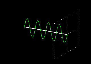
2.3. Beamwidth
– Beamwidth refers to the angular width of the main lobe of the antenna radiation pattern.
– Narrow beamwidth antennas are suitable for long-distance, point-to-point links, while wider beamwidth antennas are better for short-range, point-to-multipoint links.
2.4. Polarization
– Polarization indicates the orientation of the electromagnetic wave (vertical, horizontal, or circular).
– Ensure compatibility with the polarization of the transmitting and receiving equipment.
2.5. Environmental Considerations
– Consider environmental factors such as wind load, temperature range, and potential obstructions.
– Choose antennas with appropriate radomes and mounting hardware for harsh environments.
2.6. Regulatory Compliance
– Ensure the antenna complies with relevant regulatory standards and certifications (e.g., FCC, ETSI).
3. Types of Microwave Antennas
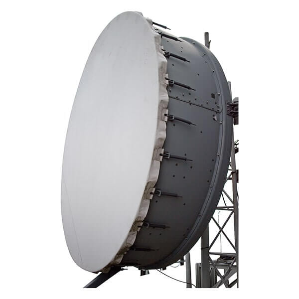
Parabolic Dish Antennas

Description: Consist of a parabolic reflector that focuses the signal into a narrow beam.
Applications: Ideal for long-distance, high-capacity point-to-point links.
Advantages: High gain, narrow beamwidth, excellent performance.
Disadvantages: Larger size, more difficult to install and align.
4. Practical Tips for Choosing the Right Antenna
4.1. Define Your Requirements
cURL Too many subrequests.
cURL Too many subrequests.
cURL Too many subrequests.
cURL Too many subrequests.
cURL Too many subrequests.
cURL Too many subrequests.
cURL Too many subrequests.
cURL Too many subrequests.
cURL Too many subrequests.
cURL Too many subrequests.
cURL Too many subrequests.
cURL Too many subrequests.
cURL Too many subrequests.
cURL Too many subrequests.
cURL Too many subrequests.
cURL Too many subrequests.
cURL Too many subrequests.
1. cURL Too many subrequests. cURL Too many subrequests.
Applications: Wi-Fi (Wi-Fi 6E), fixed wireless access, and small cell backhaul.
Characteristics: Offers a balance between range and data throughput, relatively less susceptible to rain fade compared to higher frequencies.
2. X-Band (7.125 – 8.5 GHz)
Applications: Fixed wireless communication, radar for automotive and industrial applications.
Characteristics: Good resolution for radar imaging, moderate atmospheric attenuation.
Applications: Fixed wireless access, microwave links.
Characteristics: Offers a compromise between data rate and range, moderate atmospheric attenuation.
4. 12.75 – 13.25 GHz
Applications: Fixed wireless access, point-to-point microwave communication.
Characteristics: Higher data rates compared to lower bands, but more susceptible to rain fade.
5. 14.4 – 15.35 GHz
Applications: Fixed wireless access, point-to-point microwave communication.
Characteristics: High data rates, moderate atmospheric attenuation, used for high-resolution applications.
6. 17.1 – 17.7 GHz
Applications: Fixed wireless access, point-to-point microwave communication.
Characteristics: High data rates, increased susceptibility to rain fade compared to lower frequencies.
7. 17.7 – 19.7 GHz
Applications: Fixed wireless access, point-to-point microwave communication.
Characteristics:High data rates, significant atmospheric attenuation, especially due to rain.
8. 21.2 – 23.6 GHz
Applications: High-capacity wireless backhaul, fixed wireless access.
Characteristics: Very high data rates, considerable atmospheric attenuation, used for specialized high-resolution applications.
9. 24.25 – 26.5 GHz
Applications: 5G cellular networks, high-capacity point-to-point communications.
Characteristics: Extremely high data rates, very high atmospheric attenuation, limited range.
10. 27.5 – 29.5 GHz
Applications: 5G cellular networks, high-capacity point-to-point communications.
Characteristics: Very high data rates, significant atmospheric attenuation, particularly from rain.
11. 31.8 – 33.4 GHz
Applications: Experimental wireless communications, high-resolution radar.
Characteristics: Extremely high data rates, very high atmospheric attenuation, used for specialized applications.
12. 37.0 – 40.0 GHz
Applications: 5G, short-range high-capacity communications, and some experimental uses.
Characteristics: Extremely high data rates, very high atmospheric attenuation, limited range.
13. V-Band (40.5 – 43.5 GHz)
Applications: High-capacity point-to-point communications, 5G, and some experimental uses.
Characteristics: Extremely high data rates, very high atmospheric attenuation, limited range.
14. V-Band (60 GHz)
Applications: High-capacity wireless communications, WiGig (802.11ad/ay), and some 5G applications.
Characteristics: Extremely high data rates, significant atmospheric attenuation, limited range, especially affected by oxygen absorption.
15. E-Band (71 – 86 GHz)
Applications: High-capacity point-to-point communications, backhaul for 5G, and some radar applications.
cURL Too many subrequests.
cURL Too many subrequests.
cURL Too many subrequests.

cURL Too many subrequests.
cURL Too many subrequests.
cURL Too many subrequests.
cURL Too many subrequests.
cURL Too many subrequests.
cURL Too many subrequests.
cURL Too many subrequests.
2. Interference Management:
cURL Too many subrequests.
cURL Too many subrequests.
cURL Too many subrequests.
cURL Too many subrequests.
cURL Too many subrequests.
cURL Too many subrequests.
cURL Too many subrequests.
Conclusion
Microwave frequencies above 7.125 GHz encompass a wide range of bands, each with unique characteristics and applications. Effective regulatory frameworks are essential to manage spectrum allocation, minimize interference, and support the deployment of emerging technologies. Understanding these aspects is crucial for stakeholders in telecommunications, satellite communications, and other related fields.
Principles of Microwave Transmission
Microwave transmission is a method of transmitting information using microwave frequencies, typically in the range of 7.125 GHz to 86 GHz. This method is widely used in telecommunications, broadcasting, and satellite communications due to its ability to carry large amounts of data over long distances. Understanding the principles of microwave transmission involves recognizing the importance of line-of-sight requirements and the various propagation mechanisms and challenges that affect signal quality and reliability.
Line-of-Sight Requirements
1. Direct Line-of-Sight (LOS):
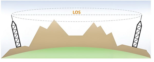
– Microwave signals travel in straight lines, so a clear, unobstructed path between the transmitting and receiving antennas is crucial.
– The Earth’s curvature can limit the effective range of line-of-sight communication. For terrestrial microwave links, the maximum distance is typically around 30-50 km, depending on the height of the antennas.
2. Fresnel Zone:
– The Fresnel zone is an elliptical area around the direct line-of-sight path that must be kept relatively clear of obstructions to avoid significant signal degradation.
– Obstructions within the Fresnel zone can cause diffraction and scattering, leading to signal attenuation and phase shifts.
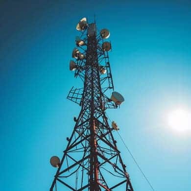
3. Antenna Placement:
– Antennas are often placed on tall structures like towers, buildings, or hills to maximize the line-of-sight range and avoid obstacles.
– The height of the antennas can significantly impact the effective communication range and the quality of the signal.
Propagation Mechanisms and Challenges
1. Free-Space Propagation:
– In ideal conditions, microwave signals propagate through free space without significant loss other than the spreading of the wavefront (free-space path loss).
– The power of the received signal decreases with the square of the distance from the transmitter.
2. Atmospheric Absorption:
– The atmosphere can absorb microwave signals, especially at higher frequencies. Water vapor and oxygen are the primary absorbers in the microwave range.
– Specific frequencies, such as those around 22 GHz (water vapor resonance) and 60 GHz (oxygen resonance), experience higher absorption rates.
3. Rain Fade:
– Precipitation, particularly rain, can cause significant attenuation of microwave signals. This phenomenon is known as rain fade.
– The extent of rain fade depends on the frequency of the signal and the intensity of the rain.
4. Multipath Propagation:
– Multipath occurs when signals reflect off surfaces like buildings, water bodies, or the ground, creating multiple paths that the signal can travel to reach the receiver.
– These reflected signals can interfere with the direct signal, causing constructive or destructive interference, leading to signal fading or distortion.
5. Diffraction:
– When a microwave signal encounters an obstacle with sharp edges, it can bend around the obstacle. This is known as diffraction.
– Diffraction can help the signal reach areas that are not in the direct line-of-sight but often results in reduced signal strength.
6. Scattering:
– Scattering occurs when the microwave signal encounters small objects or irregularities in the medium, causing the signal to spread in different directions.
– Scattering can lead to signal loss and can be caused by factors such as atmospheric turbulence, foliage, and buildings.
7. Ducting:
– Under certain atmospheric conditions, layers of the atmosphere can act as a waveguide, trapping the microwave signal and allowing it to travel over longer distances than usual.
– Ducting can cause unexpected signal strength variations and can be both beneficial and detrimental to communication.
cURL Too many subrequests.
1. Diversity Techniques:
– Using multiple antennas at different locations or polarizations can help mitigate the effects of multipath fading and improve signal reliability.
– Space diversity, frequency diversity, and polarization diversity are common techniques used in microwave communication systems.
2. Adaptive Modulation and Coding:
– Adjusting the modulation scheme and coding rate based on the current channel conditions can help maintain a reliable communication link.
– Adaptive modulation and coding (AMC) techniques allow the system to trade off between data rate and robustness.
cURL Too many subrequests.
cURL Too many subrequests.
cURL Too many subrequests.
cURL Too many subrequests.
cURL Too many subrequests.
cURL Too many subrequests.
cURL Too many subrequests.
cURL Too many subrequests.
Microwave antennas cURL Too many subrequests.
cURL Too many subrequests.
cURL Too many subrequests.
cURL Too many subrequests.
cURL Too many subrequests.
cURL Too many subrequests.
Basic Principle
cURL Too many subrequests.
Components
cURL Too many subrequests.
cURL Too many subrequests.
cURL Too many subrequests.
4. Mounting Brackets: The framework that supports the dish and allows it to be aimed in different directions. This structure often includes motors and control systems for precise positioning.
cURL Too many subrequests.
Receiving Mode
1. Signal Capture: Incoming microwaves, such as those from a satellite, strike the parabolic dish.
2. Reflection: These waves reflect off the parabolic surface and converge at the focal point, where the feed horn is located.
3. Collection: The feed horn collects the concentrated microwaves and directs them into the waveguide.
4. Transmission to Receiver: The waveguide carries the microwaves to the receiver, where they are processed and converted into usable data.
Transmitting Mode
1. Signal Generation: A microwave signal is generated by the transmitter.
2. Guidance: The signal is sent through the waveguide to the feed horn.
3. Emission: The feed horn emits the microwaves towards the parabolic reflector.
4. Reflection and Focus: The parabolic dish reflects the microwaves, directing them into a narrow, focused beam that travels parallel to the dish’s axis.
Advantages
– High Gain: Parabolic dish antennas can achieve high gain, meaning they can focus energy into a narrow beam, which allows for long-distance communication and high signal strength.
– Directivity: The narrow beamwidth provides high directivity, which is beneficial for point-to-point communication and reduces interference from other sources.
– Efficiency: The parabolic shape ensures that most of the collected energy is focused onto the feed horn, making the antenna very efficient.
Conclusion
Parabolic dish antennas are highly effective for applications requiring high gain and directivity. By leveraging the geometric properties of a parabola, these antennas can focus and direct microwave signals with great precision, making them invaluable in various advanced communication and radar systems.
Applications of Microwave Antennas
Microwave antennas are integral components in various communication systems due to their ability to handle high-frequency signals. Here are some notable applications of microwave antennas, particularly in backhaul and point-to-point communication:
Backhaul Communication
Backhaul communication refers to the transmission of data from distributed network nodes to a central node or network backbone, often over long distances. Microwave antennas are commonly used in backhaul communication for several reasons:
1. Telecommunication Networks: Microwave antennas are used to connect cellular base stations to the core network. This is crucial for mobile network operators to ensure reliable and high-capacity data transmission.
2. Internet Service Providers (ISPs): ISPs use microwave links to provide broadband services to remote or underserved areas where laying fiber optic cables may not be feasible.
3. Public Safety Networks: Emergency services and public safety organizations use microwave backhaul to ensure robust and reliable communication channels, especially in disaster-prone or rural areas.
cURL Too many subrequests.
Point-to-point communication involves a direct link between two communication nodes. Microwave antennas are ideal for such applications due to their focused beam and high data rate capabilities. Here are some common uses:
1. Private Networks: Businesses and organizations use point-to-point microwave links to connect different office locations, providing secure and high-speed data transmission without relying on public networks.
2. Military and Defense: Secure and reliable communication is critical in military operations. Microwave antennas are used for point-to-point communication to ensure encrypted and interference-resistant links.
3. Campus Networks: Universities and large enterprises often use microwave links to connect multiple buildings within a campus, facilitating seamless data transfer and communication.
4. Remote Monitoring and Control: Industries such as oil and gas, utilities, and transportation use point-to-point microwave communication for remote monitoring and control of equipment and infrastructure.
5. Surveillance and Security: High-resolution video surveillance systems often rely on microwave links to transmit video feeds from remote cameras to central monitoring stations.
Advantages of Microwave Antennas
– High Bandwidth: Capable of supporting high data rates, making them suitable for modern communication needs.
– Long Distance: Effective for long-distance communication without significant loss of signal quality.
– Low Latency: Provides low-latency communication, which is crucial for real-time applications.
– Reliability: Less susceptible to physical obstructions and interference compared to lower-frequency communication methods.
Conclusion
Microwave antennas play a critical role in both backhaul and point-to-point communication systems, offering a reliable, high-capacity, and cost-effective solution for various industries. Their ability to transmit data over long distances with minimal latency makes them indispensable in modern communication infrastructure.
Chapter 3: Key components
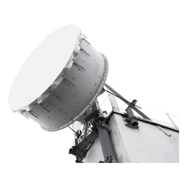
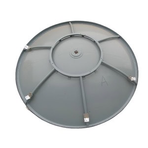
Reflector
A key component of a microwave antenna is the reflector, also known as the dish. The reflector is a curved metal surface that is designed to focus the microwave signals onto the feed horn or the receiver. The shape of the reflector is typically parabolic, which helps to direct the signals in a specific direction. The size of the reflector can vary depending on the specific application and the desired range and coverage area of the antenna. The reflector is an essential part of the antenna as it helps to increase the gain and directivity of the antenna, allowing for better signal reception and transmission.
It serves several essential functions:
1. Directing Signals: The reflector focuses the microwave signals into a narrow beam, allowing for precise targeting and reception. This is crucial for long-distance communication and for minimizing interference.
2. Amplifying Signals: By reflecting and concentrating the microwave energy, the dish effectively amplifies the signal strength, improving both transmission and reception quality.
3. Reducing Interference: The design of the dish helps to minimize the reception of unwanted signals and noise from other directions, enhancing the clarity and reliability of the communication.
Radome
cURL Too many subrequests.

cURL Too many subrequests.
cURL Too many subrequests.
cURL Too many subrequests.
cURL Too many subrequests.
cURL Too many subrequests.
cURL Too many subrequests.
cURL Too many subrequests.
cURL Too many subrequests.
Feedhorn
cURL Too many subrequests.

cURL Too many subrequests.
cURL Too many subrequests.
cURL Too many subrequests.
cURL Too many subrequests.
cURL Too many subrequests.
cURL Too many subrequests.
cURL Too many subrequests.
cURL Too many subrequests.
cURL Too many subrequests.

cURL Too many subrequests.
1. Material and Construction: Waveguides are often made from metals like copper or aluminum due to their excellent conductive properties. They can be rectangular, circular, or elliptical in cross-section.
2. Modes of Propagation: Waveguides support various modes of electromagnetic wave propagation, such as Transverse Electric (TE) and Transverse Magnetic (TM) modes. The specific mode depends on the waveguide’s dimensions and the frequency of the microwave signal.
3. Frequency Range: Waveguides are designed to operate within specific frequency ranges. Their dimensions are critical and are typically a fraction of the wavelength of the microwave signal they are intended to carry.
4. Impedance Matching: Proper impedance matching is crucial to ensure maximum power transfer and minimize reflections within the waveguide. This is often achieved using devices like impedance matching sections or tuning screws.
5. Losses: Waveguides generally have lower losses compared to other transmission media like coaxial cables, especially at higher frequencies. However, they still exhibit some loss due to the finite conductivity of the metal walls and dielectric losses if filled with a dielectric material.
Understanding the role and design of waveguides is fundamental for engineers working with microwave antennas and high-frequency communication systems.
Waveguide Types
Waveguides come in various types, each suited for specific applications and frequency ranges. Here are some common types of waveguides used in microwave antenna systems:
1. Rectangular Waveguide:
– Description: The most common type, characterized by its rectangular cross-section.
– Applications: Widely used in radar systems, satellite communications, and microwave transmission lines.
– Modes: Typically supports TE (Transverse Electric) modes, with TE10 being the dominant mode.
2. Circular Waveguide:
– Description: Features a circular cross-section, which can support both TE and TM (Transverse Magnetic) modes.
– Applications: Often used in high-power applications and where rotational symmetry is beneficial.
– Modes: The dominant mode is usually TE11.
3. Elliptical Waveguide:
– Description: Has an elliptical cross-section, combining some advantages of both rectangular and circular waveguides.
– Applications: Used in specific applications where the unique properties of elliptical shapes are advantageous.
– Modes: Supports hybrid modes, which are combinations of TE and TM modes.
4. Flexible Waveguide:

– Description: Made from a corrugated metal tube, allowing flexibility and ease of routing.
– Applications: Used in situations where rigid waveguides are impractical, such as in mobile or rotating systems.
– Modes: Typically supports the same modes as their rigid counterparts, but with slightly higher losses.
5. Ridged Waveguide:

– Description: Contains ridges along the interior walls, which lower the cutoff frequency and allow for a wider bandwidth.
– Applications: Used in broadband applications where a wide frequency range is required.
– Modes: Can support TE and TM modes, with the ridges modifying the mode structure.
6. Dielectric Waveguide:
– Description: Uses a dielectric material to guide the waves, rather than a hollow metal tube.
– Applications: Common in integrated circuits and photonics.
– Modes: Supports hybrid modes, often used in millimeter-wave and optical frequencies.
7. Coaxial Waveguide:
– Description: Consists of a central conductor surrounded by a cylindrical outer conductor, with dielectric material in between.
– Applications: Used in applications requiring high power handling and low loss.
– Modes: Supports TEM (Transverse Electromagnetic) mode, which is unique to coaxial structures.
8. Substrate Integrated Waveguide (SIW):
– Description: A planar form of waveguide integrated into a substrate, combining the benefits of planar circuits and traditional waveguides.
– Applications: Used in compact microwave and millimeter-wave circuits.
– Modes: Supports TE modes, similar to traditional waveguides.
Each type of waveguide has its own set of characteristics, making it suitable for different applications and frequency ranges. The choice of waveguide type depends on factors such as the required frequency range, power handling, physical size constraints, and specific application needs.
Flange
cURL Too many subrequests.
cURL Too many subrequests.
cURL Too many subrequests.
cURL Too many subrequests.
cURL Too many subrequests.
cURL Too many subrequests.
cURL Too many subrequests.
cURL Too many subrequests.
cURL Too many subrequests.
cURL Too many subrequests.
cURL Too many subrequests.
cURL Too many subrequests.
cURL Too many subrequests.
cURL Too many subrequests.
cURL Too many subrequests.
cURL Too many subrequests.
cURL Too many subrequests.
cURL Too many subrequests.
cURL Too many subrequests.
– Coaxial Flanges: Used to connect coaxial cables to waveguides or other components.
– Double Ridge Waveguide Flanges: Used with double ridge waveguides, which can handle a wider bandwidth.
2. Standards for Flanges:
– IEC (International Electrotechnical Commission): Provides international standards for waveguide flanges, such as IEC 60154.
– MIL-DTL-3922: A U.S. military standard specifying the dimensions and performance of waveguide flanges.
– EIA (Electronic Industries Alliance): Provides standards for coaxial and waveguide components.
– UG (Universal Guide): A series of standardized flanges (e.g., UG-39/U, UG-149/U) commonly used in the industry.
Common Flange Standards
– WR (Waveguide Rectangular) Series: For example, WR-90, WR-75, WR-28, etc., each corresponding to specific frequency ranges.
– CPR (Cover Plate Rectangular) Flanges: These flanges are often used in applications requiring a weatherproof seal.
– PDR (Pressure Door Rectangular) Flanges: Used in high-pressure applications.
Flange Designations
Flanges are typically designated by a combination of letters and numbers that indicate their type, size, and standard. For example:
– WR-90: A rectangular waveguide flange for X-band frequencies.
– UG-39/U: A specific type of flange standardized by the Universal Guide.
Conclusion
Flanges are critical components in microwave antenna systems, ensuring proper connection and minimal signal loss. Understanding the types and standards of flanges is essential for designing and maintaining efficient microwave communication systems. By adhering to established standards, engineers can ensure compatibility and optimal performance across various components and systems.
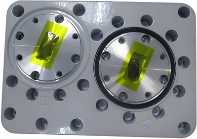
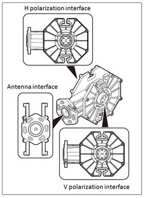
OMT (Orthomode Transducer)
The Orthomode Transducer (OMT) is a key component of microwave antennas, particularly in applications such as satellite communications, radar systems, and radio astronomy. The OMT serves to separate or combine signals based on their polarization, allowing for efficient use of the electromagnetic spectrum and enhancing the performance of the antenna system. Here are some details about the OMT and its role in microwave antennas:
Function of OMT
1. Polarization Separation: The OMT separates incoming signals based on their polarization, typically distinguishing between horizontal and vertical polarizations or left-hand and right-hand circular polarizations. This is crucial for systems that need to handle multiple signals simultaneously without interference.
2. Signal Combination: In transmission, the OMT can combine signals of different polarizations into a single feed, which is then radiated by the antenna. This is useful in maximizing the efficiency and capacity of the communication system.
Key Feature
– High Isolation: OMTs are designed to provide high isolation between the orthogonal polarizations, minimizing cross-talk and ensuring signal integrity.
– Low Insertion Loss: Minimizing the loss of signal power as it passes through the OMT is critical for maintaining the overall efficiency of the antenna system.
– Broadband Operation: Many OMTs are designed to operate over a wide frequency range, making them versatile for various applications.
Construction
OMTs are typically constructed using waveguide technology, which is well-suited for handling high-frequency microwave signals with minimal loss. The design often involves carefully engineered junctions and transitions to ensure the desired separation or combination of polarized signals.
In summary, the Orthomode Transducer (OMT) is an essential component in many microwave antenna systems, providing the capability to handle multiple polarizations efficiently and enhancing the overall performance of the system.
Mounting Brackets
This includes the mechanical parts that hold the dish and other components in place, allowing for precise alignment and stability.

They play a critical role in ensuring that the antenna is securely and accurately positioned, which is essential for optimal performance. Here are some important aspects of mounting brackets in the context of microwave antennas:
1. Stability and Support: Mounting brackets provide the necessary stability and support to the antenna, preventing it from moving or shifting due to wind, vibrations, or other environmental factors.
2. Alignment and Positioning: Proper alignment is crucial for microwave antennas to ensure that the signal is transmitted and received accurately. Mounting brackets allow for precise positioning and alignment, which is vital for maintaining the integrity of the communication link.
3. Durability: Mounting brackets are typically made from materials that can withstand harsh environmental conditions, including extreme temperatures, moisture, and corrosion. This ensures the longevity and reliability of the antenna system.
4. Adjustability: Many mounting brackets are designed to be adjustable, allowing for fine-tuning of the antenna’s position and orientation. This is particularly important during the installation process and for making adjustments to optimize performance.
5. Compatibility: Mounting brackets must be compatible with the specific type and model of the microwave antenna being used. This includes considerations for size, weight, and mounting interface.
6. Ease of Installation: A well-designed mounting bracket should facilitate easy and secure installation, reducing the time and effort required to set up the antenna system.
7. Safety: Ensuring that the antenna is securely mounted is also a safety concern. Properly designed and installed mounting brackets help prevent accidents and damage to the antenna and surrounding structures.
In summary, mounting brackets are an essential component of microwave antenna systems, providing the necessary support, alignment, and durability to ensure optimal performance and reliability.
Chapter 4: Key Factors in Antenna Selection
Gain and Directivity
Microwave antennas cURL Too many subrequests.
cURL Too many subrequests.
cURL Too many subrequests.
cURL Too many subrequests.
cURL Too many subrequests.
cURL Too many subrequests.
cURL Too many subrequests.
cURL Too many subrequests.
cURL Too many subrequests.
cURL Too many subrequests.
cURL Too many subrequests.
cURL Too many subrequests.
cURL Too many subrequests.
cURL Too many subrequests.
cURL Too many subrequests.
cURL Too many subrequests.
Polarization
cURL Too many subrequests.
cURL Too many subrequests.
cURL Too many subrequests.
cURL Too many subrequests.

cURL Too many subrequests.

– Slant Polarization: The electric field oscillates at an angle of 45°.

– Applications: Common in terrestrial microwave links, satellite communications, and radar systems.
cURL Too many subrequests.
– Right-Hand Circular Polarization (RHCP): The electric field rotates in a right-hand direction as it propagates.
– Left-Hand Circular Polarization (LHCP): The electric field rotates in a left-hand direction.
– Applications: Used in satellite communications, GPS, and mobile communications to mitigate the effects of multipath interference and signal degradation due to atmospheric conditions.
cURL Too many subrequests.
– Combines two orthogonal polarizations, typically horizontal and vertical, within the same antenna system.
– Applications: Common in MIMO (Multiple Input Multiple Output) systems, weather radar, and advanced communication systems to improve data rates and signal robustness.
Impact on Signal Quality and Interference
1. Signal Quality:
– Matching Polarization: For optimal signal reception, the polarization of the transmitting and receiving antennas should match. Mismatched polarization results in significant signal loss, known as polarization mismatch loss.
– Multipath Interference: Circular polarization can reduce the effects of multipath interference, where signals reflect off surfaces and arrive at the receiver at different times, causing signal degradation.
– Atmospheric Effects: Circular polarization is less affected by rain and atmospheric conditions compared to linear polarization, making it suitable for satellite communications.
2. Interference:
– Cross-Polarization Interference (XPI): Occurs when signals of different polarizations interfere with each other. Dual-polarized systems can separate these signals, reducing interference and improving system capacity.
– Frequency Reuse: Dual polarization allows for frequency reuse within the same geographical area, enhancing spectral efficiency and reducing interference.
– Polarization Purity: High polarization purity (low cross-polarization levels) is essential to minimize interference and ensure clean signal reception. Antennas with poor polarization purity may suffer from increased interference and degraded performance.
cURL Too many subrequests.
– Antenna Design: The design of an antenna must consider the desired polarization to ensure it effectively transmits and receives signals with minimal loss and interference.
– Environmental Factors: The choice of polarization can be influenced by environmental factors such as terrain, buildings, and weather conditions.
– System Requirements:The specific requirements of the communication system, such as data rate, range, and reliability, will determine the most suitable type of polarization.
In summary, understanding and selecting the appropriate polarization for microwave antennas is essential for optimizing signal quality, minimizing interference, and enhancing overall system performance. Each type of polarization has its advantages and is suited to different applications and environmental conditions.
cURL Too many subrequests.
Definition
VSWR (Voltage Standing Wave Ratio) is a measure of how efficiently radio-frequency power is transmitted from a power source, through a transmission line, and into a load (in this context, a microwave antenna). It is a dimensionless ratio that describes the amount of reflected power due to impedance mismatches between the transmission line and the antenna.
Mathematically, VSWR is defined as:
VSWR= (1 + | Γ |)/(1 – | Γ |) or in terms of s-parameters: VSWR= (1 + | S11 |)/(1 – | S11 |)
Importance
1. Efficiency: A low VSWR indicates that most of the power sent by the transmitter is being radiated by the antenna, rather than being reflected back. This ensures efficient operation of the antenna system.
2. Power Handling: High VSWR can lead to excessive power being reflected back to the transmitter, which can cause overheating and damage to the transmitter and other components in the transmission line.
3. Signal Integrity: High VSWR can cause signal degradation, leading to poor communication quality, reduced range, and increased error rates.
4. System Longevity: Maintaining a low VSWR helps in prolonging the life of the transmission system by reducing stress on components.
Acceptable VSWR Values for Efficient Operation
The acceptable VSWR values can vary depending on the specific application and the tolerance of the equipment used. However, general guidelines are as follows:
1. Ideal VSWR: 1:1
– This indicates perfect impedance matching, with no reflected power. This is theoretically ideal but practically difficult to achieve.
2. Good VSWR: 1.0 to 1.5
– A VSWR in this range is considered excellent. Most of the power is being effectively radiated, and losses are minimal.
3. Acceptable VSWR: 1.5 to 2.0
– This is typically acceptable for many practical applications. While some power is reflected, it is usually within tolerable limits for most equipment.
4. Marginal VSWR: 2.0 to 3.0
– This range indicates a noticeable amount of reflected power. While it may still be usable, it is generally advisable to improve the matching to avoid potential issues.
5. High VSWR: Greater than 3.0
– A VSWR higher than 3.0 indicates significant power reflection. This can lead to inefficient operation, potential damage to the transmitter, and degraded signal quality. Immediate corrective action is usually recommended.
Conclusion
VSWR is a critical parameter in the design and operation of microwave antenna systems. Maintaining a low VSWR ensures efficient power transfer, protects equipment, and ensures high-quality signal transmission. While the ideal VSWR is 1:1, values up to 2:1 are generally acceptable for most practical applications. Values higher than this typically require attention to improve impedance matching and ensure reliable system performance.
cURL Too many subrequests.
cURL Too many subrequests.
cURL Too many subrequests.
cURL Too many subrequests.
cURL Too many subrequests.

cURL Too many subrequests.
cURL Too many subrequests.
cURL Too many subrequests.
cURL Too many subrequests.
cURL Too many subrequests.
cURL Too many subrequests.
cURL Too many subrequests.
cURL Too many subrequests.
cURL Too many subrequests.
cURL Too many subrequests.
cURL Too many subrequests.
cURL Too many subrequests.
cURL Too many subrequests.
cURL Too many subrequests.
2. Interference Management:
– By understanding the RPE, engineers can design antennas that minimize interference with other systems and optimize performance in the desired directions.
3. Antenna Performance:
– The RPE helps in assessing the efficiency and effectiveness of an antenna. It provides insights into how well the antenna focuses energy in the desired direction and suppresses it in undesired directions.
4. Design Optimization:
– Engineers use the RPE to optimize the design of antennas. By analyzing the envelope, they can make adjustments to the antenna structure to improve its radiation characteristics.
Analyzing RPE
1. Plotting:
– RPE is typically plotted on a polar or Cartesian coordinate system. The radial distance from the origin represents the relative power level, and the angle represents the direction of radiation.
2. Measurement:
– The RPE can be measured using various techniques, including anechoic chamber measurements and field tests. These measurements are then compared to the theoretical or desired envelope.
3. Simulation:
– Modern antenna design often involves computer simulations to predict the RPE. Software tools like HFSS, CST Microwave Studio, and others are used to simulate and visualize the radiation patterns.
Conclusion
The Radiation Pattern Envelope is a vital tool for understanding and optimizing the performance of microwave antennas. It helps ensure that antennas meet regulatory standards, minimize interference, and perform efficiently in their intended applications. By carefully analyzing and designing around the RPE, engineers can develop antennas that meet the stringent requirements of modern communication systems.
ISO(Isolation)
Isolation in microwave antennas refers to the ability of an antenna system to prevent unwanted coupling between different antenna elements or between the antenna and other components in the system. High isolation is important to ensure that the signals transmitted or received by one antenna do not interfere with the signals of another antenna or with other electronic components. This is crucial in applications where multiple antennas are used in close proximity, such as in MIMO (Multiple Input Multiple Output) systems, satellite communications, and radar systems.

Here are some key points about isolation in microwave antennas:
1. Decoupling Techniques: Various techniques can be employed to improve isolation, such as spatial separation, polarization diversity, and the use of decoupling networks or structures. For example, placing antennas at an optimal distance apart can reduce mutual coupling.
2. Design Considerations: The design of the antenna itself can influence isolation. For instance, using directional antennas can help to focus the radiation pattern away from other antennas, thus reducing interference.
3. Material and Shielding: The use of materials with specific electromagnetic properties and physical shielding can also enhance isolation. For example, using absorptive materials or metallic shields can block unwanted signals.
4. Frequency Planning: Careful frequency planning and channel allocation can minimize interference and improve isolation. Ensuring that antennas operating at different frequencies or with different bandwidths are properly managed can reduce potential overlap.
5. Simulation and Testing: Advanced simulation tools can model the electromagnetic behavior of antenna systems and predict isolation performance. Physical testing and measurement in anechoic chambers or other controlled environments are also essential to validate isolation characteristics.
6. Isolation Metrics: Isolation is typically measured in decibels (dB) and represents the ratio of the power received by one antenna to the power transmitted by another. Higher dB values indicate better isolation. For example, an isolation of 30 dB means that the received power is 30 dB lower than the transmitted power, indicating good isolation.
Improving isolation in microwave antennas is crucial for maintaining signal integrity, reducing interference, and ensuring the overall performance and reliability of communication systems.
F/B (Front-to-back ratio)
The Front-to-Back (F/B) ratio of a microwave antenna is an important parameter that measures the directional performance of the antenna. It is defined as the ratio of the power radiated in the main lobe (the forward direction) to the power radiated in the opposite direction (the back lobe). This ratio is usually expressed in decibels (dB).
Mathematically, the F/B ratio can be expressed as:

A higher F/B ratio indicates that the antenna is more directional, meaning it radiates more power in the desired forward direction and less in the unwanted backward direction. This is particularly important in applications where minimizing interference and maximizing signal strength in a specific direction is crucial, such as in point-to-point communication links, radar systems, and satellite communications.
For example, an F/B ratio of 20 dB means that the power radiated in the forward direction is 100 times greater than the power radiated in the backward direction.
When designing or selecting an antenna, the F/B ratio is one of the key specifications to consider, alongside other parameters such as gain, beamwidth, and polarization.
ODU (Outdoor Radio Unit) Mount Type
Microwave antennas and Outdoor Radio Units (ODUs) are critical components in wireless communication systems, particularly for point-to-point and point-to-multipoint microwave links. Here’s a detailed look at some of the key brands and the differences between direct mount and split mount configurations.
ODU Brands
Several reputable brands manufacture microwave antennas and ODUs. Here are a few notable ones:
1. Ericsson
– Known for high-performance microwave solutions.
– Offers a range of microwave products including MINI-LINK series.
2. Huawei
– Provides comprehensive microwave solutions.
– Known for its RTN series of microwave products.
– Popular for cost-effective and reliable microwave solutions.
– Offers airFiber series for high-capacity backhaul.
– Known for its PTP (Point-to-Point) and PMP (Point-to-Multipoint) solutions.
– Offers PTP 820 and PTP 850 series.
cURL Too many subrequests.
cURL Too many subrequests.
cURL Too many subrequests.
cURL Too many subrequests.
cURL Too many subrequests.
cURL Too many subrequests.
cURL Too many subrequests.
Direct Mount
cURL Too many subrequests.

Advantages
cURL Too many subrequests.
cURL Too many subrequests.
cURL Too many subrequests.
Disadvantages
cURL Too many subrequests.
cURL Too many subrequests.
Split Mount
cURL Too many subrequests.

Advantages
– Ease of Maintenance: Since the ODU is more accessible, maintenance and replacements are easier.
– Better Heat Management: The ODU can be placed in a cooler, more controlled environment, improving its longevity and performance.
– Flexibility: Allows for more flexible installations, especially in environments where space is a concern.
Disadvantages
– Increased Losses: The separation between the ODU and the antenna can introduce additional losses due to the cabling.
– Complex Installation: More components and cabling can make the installation process more complex and time-consuming.
Conclusion
Choosing between direct mount and split mount configurations depends on the specific requirements of the installation, including factors like ease of maintenance, environmental conditions, and installation complexity. Each brand offers unique features and benefits, so it’s essential to evaluate your specific needs and budget when selecting a microwave antenna and ODU solution.
Antenna Size and Weight
When considering microwave antennas, their size and weight are critical factors that impact their installation, maintenance, and overall effectiveness. Here are key points to consider:
Physical Constraints and Mounting Considerations
Antenna Size
– Frequency and Gain: Higher frequency antennas typically have smaller dimensions due to shorter wavelengths. Conversely, to achieve higher gain, antennas usually need to be larger.
– Space Availability: The physical space available for mounting the antenna can limit the size. Rooftops, towers, and masts have finite space and structural capacity.
– Wind Load: Larger antennas present a greater surface area, which can be affected by wind load, requiring robust mounting structures and potentially increasing the risk of wind-induced vibrations or damage.
Antenna Weight
– Structural Support: Heavier antennas require stronger mounting structures. This can increase the cost and complexity of the installation.
– Transport and Handling: Heavier and bulkier antennas can be more challenging to transport and handle, necessitating specialized equipment and more personnel for installation.
– Balance and Stability: The weight distribution of the antenna must be carefully managed to ensure stability, especially on high towers or poles.
Impact on Installation and Maintenance
Installation
– Site Survey: A thorough site survey is essential to assess the feasibility of installing large or heavy antennas. This includes evaluating the structural integrity of the mounting location.
– Permits and Regulations: Larger installations may require specific permits and adherence to local regulations, which can add time and cost to the project.
– Safety: The installation of large or heavy antennas involves significant safety considerations, including the risk of falls, handling heavy equipment, and working at heights.
Maintenance
– Accessibility: Larger antennas may be more difficult to access for routine maintenance and repairs, particularly if they are mounted at great heights or in confined spaces.
– Wear and Tear: The physical size and weight can affect the wear and tear on both the antenna and its mounting structure, potentially leading to more frequent maintenance needs.
– Replacement Parts: Larger antennas might have more specialized components, which can be harder to source and replace, leading to longer downtimes.
Practical Tips
1. Pre-Installation Planning: Conduct comprehensive planning that includes load calculations, structural analysis, and a detailed site survey.
2. Modular Designs: Consider modular antenna designs that can be assembled on-site, reducing transportation challenges.
3. Regular Inspections: Implement a schedule for regular inspections to identify and address potential issues before they lead to significant problems.
4. Training: Ensure that installation and maintenance personnel are well-trained and equipped to handle the specific challenges posed by the size and weight of the antennas.
5. Technology Integration: Utilize technology such as drones for inspections and maintenance to reduce the need for physical access, especially in difficult-to-reach areas.
By carefully considering these factors, you can optimize the installation and maintenance of microwave antennas, ensuring reliable performance and minimizing potential issues related to their size and weight.
Environmental Considerations
When designing and deploying microwave antennas, environmental considerations are critical to ensure reliable performance and longevity. Here are some key aspects to consider:
Weatherproofing and Durability
1. Radome Design:
– Sealed Radome: Use enclosures with high ingress protection (IP) ratings, such as IP65 or higher, to prevent water and dust from entering the antenna system.
– Material Selection: Choose materials that are resistant to corrosion, UV radiation, and physical wear and tear. Common materials include aluminum with protective coatings, and high-quality plastics.
2. Gaskets and Seals:
– Weatherproof Gaskets: Use neoprene or silicone gaskets to seal joints and connections, preventing water ingress.
– O-rings: Implement O-rings in connectors and entry points to ensure a tight seal.
3. Coatings and Treatments:
cURL Too many subrequests.
cURL Too many subrequests.
4. Mounting Hardware:
cURL Too many subrequests.
cURL Too many subrequests.
cURL Too many subrequests.
cURL Too many subrequests.
cURL Too many subrequests.
cURL Too many subrequests.
cURL Too many subrequests.
cURL Too many subrequests.
cURL Too many subrequests.
cURL Too many subrequests.
cURL Too many subrequests.
cURL Too many subrequests.
cURL Too many subrequests.
cURL Too many subrequests.
cURL Too many subrequests.
Additional Considerations
cURL Too many subrequests.
cURL Too many subrequests.
– Surge Protectors: Install surge protectors to safeguard electronic components from voltage spikes.
2. Wind Load:
– Structural Design: Ensure the antenna and its mounting structure can withstand high wind speeds, especially in hurricane-prone areas.
– Aerodynamic Shapes: Consider aerodynamic designs to reduce wind resistance and minimize mechanical stress.
3. Ice and Snow:
– De-Icing Solutions: Implement de-icing or anti-icing systems, such as heating elements, to prevent ice buildup.
– Snow Shields: Use snow shields or covers to protect the antenna from snow accumulation.
By addressing these environmental considerations, you can enhance the reliability and durability of microwave antennas, ensuring consistent performance even in harsh conditions.
Chapter 5: Installation and Alignment
Site Survey and Preparation
Conducting a site survey and preparing the installation site are crucial steps in setting up a microwave antenna system. Proper planning ensures optimal performance, safety, and compliance with regulations. Below are the steps involved in conducting a site survey and preparing the installation site.
Conducting a Site Survey
1. Pre-Survey Planning:
– Objective Definition: Clearly define the purpose of the microwave link, such as data transmission, voice communication, or video broadcasting.
– Gather Requirements: Understand the bandwidth, frequency, and distance requirements for the link.
2. Site Selection:
– Location Identification: Identify potential sites for the antenna installation, considering both ends of the microwave link.
– Access and Permissions: Ensure you have access to the sites and obtain necessary permissions from property owners or authorities.
3. Line-of-Sight (LOS) Analysis:
– Visual Inspection: Perform a visual inspection to ensure there are no obstructions like buildings, trees, or hills between the two sites.
– Geographical Tools: Use tools like topographical maps, GPS, and software (e.g., Google Earth, Pathloss) to confirm the line of sight.
– Fresnel Zone Clearance: Ensure that the first Fresnel zone is clear of obstacles to minimize signal attenuation.
4. Signal Interference Check:
– Frequency Coordination: Check for existing microwave links in the area to avoid frequency interference.
– Spectrum Analysis: Use a spectrum analyzer to detect potential sources of interference.
5. Environmental Considerations:
– Weather Impact: Assess the impact of weather conditions such as rain, snow, and fog on signal propagation.
– Structural Stability: Evaluate the structural stability of existing buildings or towers where the antenna will be mounted.
cURL Too many subrequests.
– Power Availability: Ensure there is a reliable power source at the site.
– Grounding: Plan for proper grounding to protect equipment from electrical surges.
7. Documentation:
– Survey Report: Document all findings, including site coordinates, photos, LOS diagrams, and interference analysis.
– Regulatory Compliance: Ensure compliance with local regulations and obtain necessary permits.
Preparing the Installation Site
1. Site Preparation:
– Clearing Obstacles: Remove any physical obstructions identified during the survey.
– Foundation Work: Prepare the foundation for the antenna mast or tower, ensuring it is stable and level.
2. Antenna Mounting Structure:
– Tower Erection: If a new tower is required, erect it according to the manufacturer’s specifications and safety standards.
– Mounting Brackets: Install mounting brackets securely on existing structures.
3. Antenna and ODU Installation:
3.1 Antenna Alignment:
cURL Too many subrequests.
cURL Too many subrequests.
cURL Too many subrequests.
cURL Too many subrequests.
cURL Too many subrequests.
cURL Too many subrequests.
cURL Too many subrequests.
cURL Too many subrequests.
cURL Too many subrequests.
cURL Too many subrequests.
cURL Too many subrequests.
cURL Too many subrequests.
cURL Too many subrequests.
cURL Too many subrequests.
cURL Too many subrequests.
cURL Too many subrequests.
cURL Too many subrequests.
cURL Too many subrequests.
cURL Too many subrequests.
4. Power and Grounding:
– Power Connection: Connect the antenna system to the power source, ensuring all connections are secure.
– Grounding: Implement grounding measures to protect against lightning and electrical surges.
5. Testing and Calibration:
– Initial Testing: Perform initial power-up and basic functionality tests.
– Signal Strength: Measure and adjust the signal strength to achieve optimal performance.
– Final Calibration: Fine-tune the antenna alignment and settings for maximum efficiency.
6. Safety and Compliance:
– Safety Checks: Conduct safety checks to ensure all installations are secure and comply with safety standards.
– Regulatory Compliance: Verify that the installation meets all regulatory requirements and standards.
7. Documentation and Handover:
– Installation Report: Document the installation process, including alignment data, test results, and any issues encountered.
– Handover: Provide the client or site owner with documentation and training on the system’s operation and maintenance.
By following these steps, you can ensure a successful microwave antenna installation that meets performance, safety, and regulatory standards.
Mounting and Securing the Antenna
Mounting and securing a microwave antenna is critical to ensure optimal performance, safety, and longevity. Here’s a detailed overview covering the types of mounting hardware and best practices for ensuring stability and security:
Types of Mounting Hardware
1. Pole Mounts:
– Standard Pole Mounts: Used for mounting antennas on poles, typically featuring U-bolts or clamps to secure the antenna to the pole.

– Tilt and Swivel Mounts: Allow for adjustment of the antenna’s angle and direction, providing flexibility in aiming the antenna.
– Non-Penetrating Roof Mounts:** Designed to sit on flat roofs without penetrating the roofing material, often weighted down with cinder blocks or other heavy objects.
2. Wall Mounts:
– Standard Wall Brackets: Fixed brackets that mount directly onto a wall, providing a stable platform for the antenna.
– Adjustable Wall Mounts: Allow for some degree of movement and adjustment to optimize signal reception.

3. Tripod Mounts:
– Roof Tripods: Typically used on flat or slightly sloped roofs, offering a stable base for antennas.
– Ground Tripods: Portable and can be used on various surfaces, providing flexibility in placement.
4. Tower Mounts:
– Tower Sections: Modular sections that can be assembled to create a tall structure for mounting antennas.
– Tower Brackets: Used to attach antennas to existing towers, ensuring a secure fit.
Ensuring Stability and Security
1. Structural Integrity:
– Material Quality: Use high-quality, corrosion-resistant materials (e.g., galvanized steel, stainless steel) to prevent degradation over time.
– Load Capacity: Ensure the mounting hardware can handle the weight and wind load of the antenna, including any additional equipment like radomes or feed horns.
2. Proper Installation:
– Leveling: Ensure the mount is level and properly aligned to avoid signal degradation.
– Secure Fastening: Use appropriate fasteners (e.g., bolts, screws) and ensure they are tightened to the manufacturer’s specifications.
– Redundancy: Consider using lock washers or thread-locking compounds to prevent fasteners from loosening over time.
3. Environmental Considerations:
– Wind Resistance: Ensure the mount and antenna can withstand local wind conditions, including gusts and storms.
– Seismic Considerations: In earthquake-prone areas, additional bracing or damping mechanisms may be necessary to prevent damage.
cURL Too many subrequests.
cURL Too many subrequests.
cURL Too many subrequests.
cURL Too many subrequests.
cURL Too many subrequests.
cURL Too many subrequests.
cURL Too many subrequests.
cURL Too many subrequests.
cURL Too many subrequests.
cURL Too many subrequests.
cURL Too many subrequests.
cURL Too many subrequests.
cURL Too many subrequests.
cURL Too many subrequests.
cURL Too many subrequests.
cURL Too many subrequests.
cURL Too many subrequests.
cURL Too many subrequests.
cURL Too many subrequests.
– Elevation Alignment: Adjust the vertical angle to ensure the antenna is pointing at the correct height.
3. Signal Strength Measurement:
– Spectrum Analyzer: Measure the signal strength and quality to ensure the antenna is properly aligned.
– Signal Meters: Use signal strength meters to find the peak signal during alignment.
4. Two-Way Communication:
– Walkie-Talkies or Mobile Phones: Coordinate with a partner at the other end to make real-time adjustments.
– Remote Monitoring: Use remote monitoring systems to observe signal changes during alignment.
5. Polarization Adjustment:
– Cross-Polarization Isolation: Adjust the antenna to match the polarization of the transmitted signal, reducing interference and improving signal quality.
6. Fine-Tuning:
– Incremental Adjustments: Make small incremental adjustments to azimuth, elevation, and polarization while monitoring signal strength.
– Locking Mechanisms: Once aligned, secure the antenna using locking mechanisms to maintain alignment.
Tools and Equipment for Calibration
1. Spectrum Analyzers:
– Function: Measure and analyze the frequency spectrum of the signal.
– Use: Identify signal strength, interference, and noise levels.
2. Signal Generators:
– Function: Generate a known signal for testing and calibration.
– Use: Verify the antenna’s response and ensure accurate alignment.
3. Power Meters:
– Function: Measure the power of the transmitted and received signals.
– Use: Ensure the antenna is transmitting and receiving at optimal power levels.
4. GPS Devices:
– Function: Provide precise location and orientation data.
– Use: Assist in initial rough alignment and positioning of the antenna.
5. Inclinometers:
– Function: Measure the angle of inclination.
– Use: Ensure accurate elevation adjustment.
6. Laser Rangefinders:
– Function: Measure the distance to the target.
– Use: Confirm the correct distance and line-of-sight alignment.
7. Calibration Kits:
– Function: Provide a set of tools for calibrating the antenna system.
– Use: Perform regular maintenance and calibration to ensure long-term accuracy.
8. Network Analyzers:
– Function: Measure the network parameters such as S-parameters.
– Use: Ensure the antenna system is functioning correctly within the desired frequency range.
9. Field Strength Meters:
– Function: Measure the strength of the electromagnetic field.
– Use: Verify signal coverage and strength in the field.
10. Alignment Tools:
cURL Too many subrequests.
cURL Too many subrequests.
cURL Too many subrequests.
cURL Too many subrequests.
cURL Too many subrequests.
cURL Too many subrequests.
cURL Too many subrequests.
cURL Too many subrequests.
cURL Too many subrequests.
cURL Too many subrequests.
Identifying Sources of Interference
cURL Too many subrequests.
cURL Too many subrequests.
cURL Too many subrequests.
cURL Too many subrequests.
cURL Too many subrequests.
cURL Too many subrequests.
cURL Too many subrequests.
cURL Too many subrequests.
cURL Too many subrequests.
cURL Too many subrequests.
Strategies to Minimize Impact
1. Site Selection and Antenna Placement:
– Line of Sight: Ensure a clear line of sight between transmitting and receiving antennas to minimize obstructions.
– Elevation: Place antennas at higher elevations to avoid ground-based obstructions and reduce multipath interference.
– Separation: Maintain adequate physical separation from other transmitting devices and sources of interference.
2. Antenna Design and Selection:
– Directional Antennas:Use Ultra high performance dish antennas to focus the signal and reduce susceptibility to off-axis interference.
– Polarization: Employ different polarization schemes (vertical, horizontal, or dual) to minimize cross-polarization interference.
– Antenna Gain: Select antennas with appropriate gain to ensure strong signal reception while minimizing the reception of unwanted signals.
3. Frequency Management:
– Frequency Planning: Carefully plan and coordinate frequencies to avoid overlap with other systems.
– Channel Selection: Use channels with minimal interference and consider dynamic frequency selection (DFS) to automatically switch to cleaner channels.
– Guard Bands: Implement guard bands to provide a buffer zone between adjacent channels.
4. Signal Processing Techniques:
– Filtering: Use high-quality bandpass filters to block out-of-band interference.
– Adaptive Filtering: Implement adaptive filtering algorithms to dynamically adjust filter parameters based on the interference environment.
– Error Correction: Employ forward error correction (FEC) techniques to detect and correct errors caused by interference.
5. Shielding and Grounding:
– Shielding: Use shielded cables and enclosures to prevent external electromagnetic interference.
– Grounding: Ensure proper grounding of all equipment to reduce electrical noise and potential differences.
6. Interference Detection and Monitoring:
– Spectrum Analyzers: Use spectrum analyzers to identify and monitor sources of interference.
– Interference Tracking: Implement systems to track and log interference events for further analysis.
– Remote Monitoring: Use remote monitoring tools to continuously assess the interference environment and take timely corrective actions.
7. Regulatory Compliance:
– Licensing: Ensure all equipment operates within the licensed frequency bands and adheres to regulatory standards.
– Coordination: Coordinate with other users and regulatory bodies to manage and mitigate interference.
By combining these strategies, you can effectively mitigate interference and enhance the performance and reliability of microwave communication systems.
Chapter 6: Case Studies and Applications
Urban Backhaul Networks

Challenges and Solutions
1. Line-of-Sight (LoS) Requirements

– Challenge: Microwave antennas typically require a clear line of sight between the transmitting and receiving antennas. Urban environments often have numerous obstacles such as buildings, trees, and other infrastructure that can obstruct the signal path.
– Solution:
– Higher Frequency Bands: Utilize higher frequency bands (e.g., E-band: 70/80 GHz) that offer narrower beams and can be more easily directed around obstacles.
– Antenna Placement: Strategically place antennas on tall buildings or towers to ensure a clear line of sight.
– Adaptive Modulation: Implement adaptive modulation schemes that can dynamically adjust the transmission parameters based on the quality of the link.
cURL Too many subrequests.
– Challenge: Urban areas are saturated with various types of wireless signals, leading to potential interference that can degrade the performance of microwave backhaul links.
– Solution:
– Frequency Planning: Careful frequency planning and coordination to avoid overlapping channels.
– Directional Antennas: Use highly directional antennas to minimize the reception of unwanted signals.
– Interference Mitigation Technologies: Deploy technologies such as beamforming, which can help focus the signal and reduce interference from other sources.
3. Bandwidth and Capacity
cURL Too many subrequests.
– Solution:
cURL Too many subrequests.
cURL Too many subrequests.
cURL Too many subrequests.
cURL Too many subrequests.
cURL Too many subrequests.
– Solution:
cURL Too many subrequests.
cURL Too many subrequests.
cURL Too many subrequests.
cURL Too many subrequests.
cURL Too many subrequests.
– Solution:
cURL Too many subrequests.
cURL Too many subrequests.
cURL Too many subrequests.
cURL Too many subrequests.
cURL Too many subrequests.
cURL Too many subrequests.
cURL Too many subrequests.
cURL Too many subrequests.
– Technology: Multi-gigabit microwave links using higher-order modulation and dual-polarization antennas to maximize throughput.
3. Public Safety Networks
– Implementation: Urban public safety networks often rely on microwave backhaul to ensure reliable communication between various agencies and command centers.
– Technology: Robust, high-availability microwave links with redundancy and failover capabilities to ensure continuous operation during emergencies.
4. Enterprise Connectivity
– Implementation: Enterprises in urban areas use microwave backhaul to connect multiple office locations or to provide a backup connection to the primary fiber link.
– Technology: Point-to-point microwave links with adaptive modulation and interference mitigation to ensure high reliability and performance.
By addressing these challenges with innovative solutions, microwave antennas can effectively support the demanding requirements of urban backhaul networks, ensuring robust and high-capacity connectivity.
Rural and Remote Point-to-Point Links
Microwave antennas are critical for establishing reliable communication links in rural and remote areas where traditional wired infrastructure is either impractical or too expensive to deploy. These antennas facilitate long-distance point-to-point communication by transmitting and receiving high-frequency microwave signals.

Addressing Long-Distance Communication
1. Line-of-Sight (LoS) Requirements
– Clear Path: Microwave communication requires a clear line of sight between the transmitting and receiving antennas. This means there should be no physical obstructions like hills, buildings, or trees in the direct path of the microwave signal.
– Fresnel Zone Clearance: Ensuring the Fresnel zone (an elliptical area around the line of sight) is clear of obstacles is crucial for minimizing signal loss and maintaining a strong connection.
cURL Too many subrequests.
– Common Bands: Frequencies typically used for long-distance microwave communication include 6 GHz, 11 GHz, 18 GHz, and 23 GHz. Lower frequencies (e.g., 6 GHz) are preferred for longer distances due to their lower attenuation.
– Regulatory Considerations: Frequency selection must comply with local regulations and spectrum availability.
3. Antenna Types
– Parabolic Dish Antennas: These are the most common for long-distance links due to their high gain and narrow beamwidth, which helps in focusing the signal over long distances.
– Grid Antennas: These are lighter and can be less expensive than parabolic dishes, but they offer slightly lower gain.
4. Power and Amplification
– High-Gain Antennas: Using high-gain antennas can help in achieving longer distances by focusing the signal more effectively.
– Amplifiers: Low Noise Amplifiers (LNAs) and Power Amplifiers (PAs) can be used to boost the signal strength, improving both transmission and reception.
5. Weather Considerations
– Rain Fade: Higher frequency signals (above 10 GHz) can be significantly affected by rain. Planning for rain fade by incorporating fade margins in the link budget is essential.
– Wind and Storms: Ensuring that antennas are securely mounted and designed to withstand local weather conditions is crucial for maintaining link reliability.
cURL Too many subrequests.
1. Rural Broadband Connectivity

– Project Overview: A rural community lacking broadband access can establish a microwave link to the nearest town with fiber optic connectivity.
– Implementation:
– Site Survey: Conduct a site survey to ensure a clear line of sight between the two locations.
– Frequency Selection: Choose a frequency band that balances distance and regulatory requirements, such as 6 GHz.
– Antenna Installation: Install high-gain parabolic dish antennas on towers or high structures at both ends.
– Alignment: Use alignment tools to precisely align the antennas for optimal signal strength.
– Testing: Perform link testing to ensure the connection meets the required bandwidth and reliability standards.
2. Remote Industrial Operations
– Project Overview: A mining operation in a remote area requires a reliable communication link to its headquarters for data transmission and remote monitoring.
– Implementation:
– Site Survey: Assess the terrain and potential obstructions between the mine and headquarters.
– Frequency Selection: Select a lower frequency band (e.g., 6 GHz) to maximize range and minimize attenuation.
– Antenna Installation: Install robust parabolic dish antennas designed to withstand harsh environmental conditions.
– Power Considerations: Use high-power transmitters and amplifiers to ensure a strong signal over the long distance.
– Redundancy: Implement redundant links or backup systems to ensure continuous operation in case of equipment failure or adverse weather conditions.
3. Emergency Response Networks
– Project Overview: Establishing a temporary communication link for emergency response teams in a disaster-affected remote area.
– Implementation:
cURL Too many subrequests.
cURL Too many subrequests.
cURL Too many subrequests.
cURL Too many subrequests.
cURL Too many subrequests.
Conclusion
cURL Too many subrequests.
cURL Too many subrequests.
Microwave antennas cURL Too many subrequests.
cURL Too many subrequests.
cURL Too many subrequests.
cURL Too many subrequests.
cURL Too many subrequests.
cURL Too many subrequests.
cURL Too many subrequests.
cURL Too many subrequests.
cURL Too many subrequests.
cURL Too many subrequests.

cURL Too many subrequests.
cURL Too many subrequests.
cURL Too many subrequests.
2. Enterprise Data Center Connectivity
An enterprise with multiple data centers in different locations can use microwave antennas to ensure high-speed, redundant connections between these facilities.
– Scenario: A company with data centers located in different parts of a city.
– Solution: Using PtP microwave links to connect the data centers, ensuring data replication and backup processes are fast and reliable.
– Benefits: Reduced latency and high-speed data transfer between data centers.
3. Temporary Event Networks
Large events such as conferences, festivals, or sports events often require temporary high-speed networks. Microwave antennas can be quickly deployed to provide the necessary connectivity.
– Scenario: A large outdoor music festival requiring high-speed internet for vendors, staff, and attendees.
– Solution: Setting up PtMP microwave links to provide coverage across the event area.
– Benefits: Rapid deployment and high-bandwidth connectivity without the need for extensive infrastructure.
4. Remote Office Connectivity
Enterprises with remote offices in areas where laying fiber is not feasible can use microwave antennas to connect these offices to the main corporate network.
– Scenario: A company with a remote office in a rural area.
– Solution: Establishing a PtP microwave link from the remote office to the nearest urban area with fiber connectivity.
– Benefits: Reliable and high-speed internet access for the remote office.
Technical Considerations
1. Frequency Bands: Microwave antennas operate in various frequency bands (e.g., 6 GHz, 11 GHz, 18 GHz, 23 GHz). The choice of frequency band depends on factors such as distance, required bandwidth, and regulatory constraints.
2. Line of Sight (LoS): Microwave links require a clear line of sight between antennas. Obstacles such as buildings, trees, and hills can affect signal quality.
3. Antenna Alignment: Precise alignment of antennas is crucial for optimal performance. Professional installation and alignment are recommended.
4. Weather Conditions: Microwave links can be affected by weather conditions such as rain, fog, and snow. Higher frequency bands are more susceptible to weather-related attenuation.
5. Regulatory Compliance: Ensure compliance with local regulations regarding the use of microwave frequencies and the installation of antennas.
Conclusion
Microwave antennas offer a versatile and effective solution for high-density communication needs in enterprise and campus networks. By providing high-speed, reliable, and scalable connectivity, they enable organizations to meet the demands of modern network applications. Whether for permanent installations or temporary setups, microwave technology can play a pivotal role in ensuring robust network performance.
Emergency and Temporary Deployments
Deploying microwave antennas for emergency and temporary scenarios requires rapid deployment techniques and reliable, effective implementations. Here’s an overview of some key strategies and example implementations:

Rapid Deployment Techniques
1. Pre-configured Kits:
– Pre-assembled Components: Use pre-assembled and pre-configured kits that can be quickly transported and set up on-site. These kits typically include all necessary components such as antennas, mounting hardware, cables, and power supplies.
– Modular Design: Utilize modular designs that allow for quick assembly and disassembly, facilitating rapid deployment and redeployment as needed.
2. Quick-Deploy Mounting Solutions:
– Tripods and Portable Masts: Employ tripods or portable telescopic masts that can be quickly erected without the need for extensive ground preparation or permanent installations.
– Vehicle-Mounted Systems: Use vehicle-mounted antenna systems that can be deployed directly from a vehicle, providing mobility and rapid setup.
3. Integrated Communication Platforms:
– Self-Contained Units: Deploy self-contained communication units that integrate the microwave antenna with other necessary communication equipment (e.g., routers, power sources) in a single, portable package.
– Flyaway Kits: Utilize flyaway kits that are designed to be transported easily by air, allowing for rapid deployment in remote or disaster-stricken areas.
4. Automated Alignment and Calibration:
– Auto-Tracking Systems: Implement auto-tracking systems that automatically align the antenna to the target, reducing setup time and ensuring optimal signal quality.
– Pre-programmed Coordinates: Use systems that can be pre-programmed with coordinates and alignment parameters to expedite the setup process.
cURL Too many subrequests.
1. Disaster Relief Operations:
– Scenario: Following a natural disaster, communication infrastructure is often damaged or destroyed, necessitating the rapid deployment of temporary communication systems.
– Implementation: Deploy a vehicle-mounted microwave antenna system with auto-tracking capabilities. The vehicle can quickly move to the affected area, and the antenna can be set up and aligned within minutes to establish a communication link with a central hub or satellite.
cURL Too many subrequests.
cURL Too many subrequests.
cURL Too many subrequests.
cURL Too many subrequests.
cURL Too many subrequests.
cURL Too many subrequests.
cURL Too many subrequests.
cURL Too many subrequests.
cURL Too many subrequests.
Conclusion
cURL Too many subrequests.
cURL Too many subrequests.
cURL Too many subrequests.

cURL Too many subrequests. microwave antenna cURL Too many subrequests.
cURL Too many subrequests.
cURL Too many subrequests.
cURL Too many subrequests.
cURL Too many subrequests.
cURL Too many subrequests.
cURL Too many subrequests.
– Properties: Graphene is a single layer of carbon atoms with exceptional electrical, thermal, and mechanical properties.
– Advantages: High conductivity, flexibility, and the potential for miniaturization.
– Applications: Suitable for flexible and wearable electronics, as well as high-frequency microwave applications due to its excellent conductive properties.
3. 3D-Printed Antennas:
– Technology: Additive manufacturing allows for the creation of complex antenna geometries that are difficult or impossible to achieve with traditional manufacturing techniques.
– Benefits: Customizable designs, reduced weight, and the ability to integrate with other components seamlessly.
– Use Cases: Aerospace, defense, and consumer electronics where lightweight and bespoke designs are crucial.
4. Fractal Antennas:
– Design: These antennas use self-similar, repeating patterns at different scales, known as fractals.
– Advantages: Compact size, multi-band performance, and wideband capabilities.
– Applications: Ideal for applications requiring compact, multi-functional antennas such as mobile devices and IoT applications.
Integration with Smart Systems
1. Smart Antenna Systems:
– Definition: Smart antennas use advanced signal processing techniques to dynamically adjust their radiation patterns.

– Types: Includes adaptive arrays and multiple-input multiple-output (MIMO) systems.
– Benefits: Improved signal quality, increased capacity, and better interference management.
– Applications: Critical in modern communication systems like 5G, Wi-Fi, and satellite communications.
2. Internet of Things (IoT):
– Integration: Antennas are becoming integral components of IoT devices, requiring them to be small, efficient, and capable of operating in various environments.
– Technologies: Low-power wide-area networks (LPWAN), Zigbee, and Bluetooth are some of the technologies benefiting from advanced antenna designs.
– Challenges: Balancing size, power consumption, and performance.
3. Reconfigurable Antennas:
– Functionality: These antennas can dynamically change their frequency, radiation pattern, or polarization in response to changing conditions.
– Mechanisms: Use of MEMS (Micro-Electro-Mechanical Systems), PIN diodes, or varactors.
– Advantages: Versatility and adaptability, which are crucial for modern communication systems that require operation across multiple bands and environments.
4. Artificial Intelligence (AI) and Machine Learning (ML):
– Role: AI and ML algorithms are being used to optimize antenna design, predict performance, and manage networks.
– Applications: Enhancing the efficiency of smart antenna systems, optimizing beamforming techniques, and improving adaptive algorithms for dynamic environments.
5. Integration with 5G and Beyond:
– Requirements: 5G technology demands antennas that can support higher frequencies (mmWave), massive MIMO configurations, and beamforming capabilities.

– Innovations: Development of compact, high-gain antennas capable of supporting the high data rates and low latency required by 5G networks.
– Future: Research is ongoing into 6G technologies, which will further push the boundaries of antenna design and integration.
Conclusion
The advancements in microwave antenna technology, driven by emerging materials and innovative designs, coupled with integration into smart systems, are paving the way for more efficient, versatile, and high-performance antennas. These developments are crucial for meeting the demands of modern communication systems, IoT applications, and future technologies like 5G and beyond. As research continues, we can expect even more groundbreaking innovations in this field.
Impact of 5G and Beyond
The advent of 5G technology marks a significant leap in wireless communication, and microwave antennas play a crucial role in this evolution. As we look forward to 5G and beyond, understanding the role of microwave antennas and the future frequency bands and applications becomes essential.
Role of Microwave Antennas in 5G
1. High-Frequency Operation:
– Millimeter Waves (mmWave): 5G networks utilize higher frequency bands, particularly in the millimeter-wave spectrum (24 GHz to 100 GHz). Microwave antennas are designed to operate efficiently at these frequencies, providing the necessary bandwidth and data rates.

– Beamforming and MIMO: Advanced microwave antennas support beamforming and Multiple Input Multiple Output (MIMO) technologies, which are critical for improving signal strength, coverage, and capacity in 5G networks. Beamforming allows the antenna to focus the signal in a specific direction, enhancing performance and reducing interference.
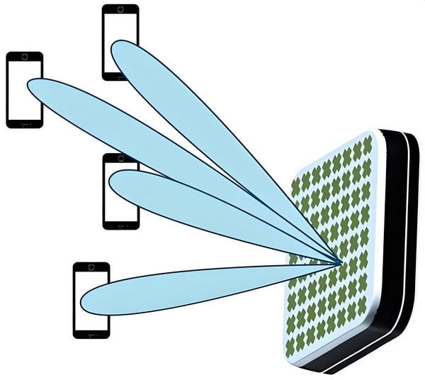
2. Small Cell Deployment:
– Dense Network Architecture: 5G requires a denser network of small cells to provide consistent coverage and high data rates. Microwave antennas are integral to these small cells, offering compact, efficient, and high-gain solutions suitable for urban environments.
cURL Too many subrequests.
cURL Too many subrequests.
cURL Too many subrequests.
cURL Too many subrequests.
cURL Too many subrequests.
cURL Too many subrequests.
cURL Too many subrequests.
cURL Too many subrequests.
cURL Too many subrequests.
cURL Too many subrequests.
cURL Too many subrequests.
cURL Too many subrequests.
cURL Too many subrequests.
cURL Too many subrequests.
Conclusion
Microwave antennas cURL Too many subrequests.
cURL Too many subrequests.
cURL Too many subrequests.

cURL Too many subrequests.
cURL Too many subrequests.
– Recycled Materials: Using recycled metals and plastics in the construction of antennas can reduce the need for virgin materials, minimizing the ecological footprint.
– Biodegradable Materials: Research into biodegradable composites for antenna components can help reduce waste and pollution.
– Non-toxic Coatings: Employing non-toxic, environmentally friendly coatings and paints can prevent harmful chemical leaching into the environment.
2. Energy Efficiency:
– Low-Power Designs: Developing antennas that operate efficiently at lower power levels can reduce energy consumption.
– Energy Harvesting: Incorporating energy-harvesting technologies, such as solar panels or ambient RF energy harvesting, can make antennas self-sufficient and reduce reliance on external power sources.
3. Manufacturing Processes:
– Green Manufacturing: Implementing green manufacturing processes that minimize waste, reduce emissions, and use renewable energy sources can make antenna production more sustainable.
– Additive Manufacturing: Utilizing 3D printing and other additive manufacturing techniques can reduce material waste and energy consumption during production.
4. Lifecycle Management:
– Modular Designs: Creating modular antennas that can be easily upgraded or repaired can extend their lifespan and reduce electronic waste.
– Recycling Programs: Establishing recycling programs for end-of-life antennas can ensure that valuable materials are recovered and reused, rather than ending up in landfills.
Reducing Environmental Impact
1. Deployment Strategies:
– Optimized Placement: Careful planning of antenna placement to minimize environmental disruption, such as avoiding sensitive ecosystems and reducing visual pollution.
– Shared Infrastructure: Encouraging the use of shared infrastructure, such as multi-tenant towers, can reduce the number of individual antennas needed, thus minimizing the environmental footprint.
2. Operational Efficiency:
– Smart Antennas: Utilizing smart antenna systems that can dynamically adjust their parameters to optimize performance and reduce energy consumption.
– Remote Monitoring and Control: Implementing remote monitoring and control systems to manage antenna operations more efficiently, reducing the need for maintenance trips and associated emissions.
3. Regulatory Compliance and Standards:
– Adhering to Environmental Standards: Ensuring that antenna designs and deployments comply with relevant environmental regulations and standards.
– Industry Certifications: Seeking certifications from recognized environmental organizations can demonstrate a commitment to sustainability and eco-friendly practices.
4. Community Engagement and Education:
– Stakeholder Engagement: Involving local communities in decision-making processes regarding antenna deployment to address environmental concerns and promote transparency.
– Educational Initiatives: Promoting awareness and education about the environmental impact of microwave antennas and the importance of sustainable practices within the industry.
Conclusion
The integration of sustainability and green technology in microwave antenna solutions is not only beneficial for the environment but also aligns with the growing demand for responsible and ethical technological advancements. By focusing on eco-friendly materials, energy efficiency, green manufacturing, and reducing the overall environmental impact, the microwave antenna industry can contribute to a more sustainable future.
Conclusion
Summary of Key Points
Choosing the right microwave antenna is crucial for ensuring optimal performance in various communication and radar systems. Here’s a comprehensive guide summarizing key points to help you make an informed decision:
1. Frequency Range
– Identify the Operating Frequency**: Ensure the antenna supports the frequency range required for your application. Microwave frequencies typically range from 7.125 GHz to 86 GHz.
2. Gain Requirements
– Determine Gain Needs: Higher gain antennas focus energy more tightly, providing longer range and better performance in point-to-point communication.
3. Beamwidth
– Narrow vs. Wide Beamwidth: Narrow beamwidth antennas are ideal for long-distance, point-to-point links, while wide beamwidth antennas are better for covering broader areas.
4. Polarization
– Linear or Circular Polarization**: Choose based on your system requirements. Linear polarization (horizontal or vertical) is common, but circular polarization can reduce signal degradation due to multipath interference.
5. Antenna Type
– Parabolic Dish: High gain, narrow beamwidth, suitable for long-distance communication.
6. Physical Size and Weight
– Consider Installation Constraints: Ensure the antenna fits within the space available and can be supported by the mounting structure.
7. Environmental Factors
– Weather Resistance: Choose antennas with appropriate IP ratings for outdoor use.
– Temperature Range: Ensure the antenna can operate within the expected temperature range.
cURL Too many subrequests.
cURL Too many subrequests.
cURL Too many subrequests.
cURL Too many subrequests.
cURL Too many subrequests.
cURL Too many subrequests.
cURL Too many subrequests.
cURL Too many subrequests.
cURL Too many subrequests.
cURL Too many subrequests.
cURL Too many subrequests.
cURL Too many subrequests.
cURL Too many subrequests.
cURL Too many subrequests.
cURL Too many subrequests.
cURL Too many subrequests.
cURL Too many subrequests.
cURL Too many subrequests.
cURL Too many subrequests.
By thoroughly evaluating these factors, you can choose the right microwave antenna that meets your specific needs and ensures optimal performance for your application.
Final Recommendations
Choosing the right microwave antenna is crucial for ensuring optimal performance in your communication system. Here are some final recommendations and best practices for antenna selection and deployment:
1. Define Your Requirements
– Frequency Range: Ensure the antenna supports the frequency range of your system.
– Gain: Higher gain antennas focus the signal more narrowly, which can improve performance over long distances.
– Beamwidth: Narrower beamwidths provide better directionality and reduced interference but require more precise alignment.
– Polarization: Choose between vertical, horizontal, or dual polarization based on your application needs.
– VSWR (Voltage Standing Wave Ratio): A lower VSWR indicates better efficiency and less signal reflection.
2. Consider Environmental Factors
– Weather Conditions: Select antennas with appropriate radomes and materials to withstand local weather conditions like rain, snow, and wind.
– Terrain: For hilly or uneven terrain, consider antennas with higher gain and narrower beamwidth to overcome obstacles.
– Interference: In urban areas with high interference, directional antennas with high front-to-back ratios can help minimize unwanted signals.
3. Evaluate Installation and Maintenance
– Mounting Options: Ensure the antenna can be securely mounted on your existing infrastructure.
– Ease of Alignment: Choose antennas with alignment aids if precise pointing is critical.
– Durability: Look for antennas with robust construction and weatherproofing to minimize maintenance.
4. Compliance and Certification
– Regulatory Compliance: Ensure the antenna complies with local and international regulations.
– Certification: Check for certifications like ISO, FCC, and CE to ensure quality and reliability.
5. Budget Considerations
– Cost vs. Performance: Balance the cost of the antenna with the performance requirements of your system.
– Total Cost of Ownership: Consider long-term costs, including maintenance and potential replacements.
6. Vendor Reputation and Support
– Vendor Reliability: Purchase from reputable vendors with a track record of quality and reliability.
– Technical Support: Ensure the vendor offers robust technical support and warranty services.
Best Practices for Deployment
– Site Survey: Conduct a thorough site survey to identify potential obstacles and sources of interference.
– Proper Alignment: Use professional tools and techniques for precise alignment to maximize performance.
– Regular Maintenance: Schedule regular maintenance checks to ensure the antenna and associated equipment are in good working condition.
– Documentation: Keep detailed records of installation, alignment, and maintenance activities.
– Training: Ensure your team is trained in both the technical and safety aspects of antenna installation and maintenance.
By following these recommendations and best practices, you can ensure that you select and deploy the most suitable microwave antenna for your communication needs, leading to enhanced performance and reliability.
Resources for Further Reading
Books

1. “Microwave Engineering” by David M. Pozar
– Comprehensive coverage of microwave theory, design, and applications.
2. “Antenna Theory: Analysis and Design” by Constantine A. Balanis
– In-depth exploration of antenna principles, including microwave antennas.
Papers and Articles
1. “Design and Analysis of Microwave Antennas” by Prof. Amitabha Bhattacharya | IIT Kharagpur
cURL Too many subrequests.
2. “cURL Too many subrequests.”cURL Too many subrequests.
cURL Too many subrequests.
cURL Too many subrequests.
cURL Too many subrequests.
cURL Too many subrequests.cURL Too many subrequests.)
cURL Too many subrequests.
cURL Too many subrequests.cURL Too many subrequests.)
cURL Too many subrequests.
Appendices
cURL Too many subrequests.
cURL Too many subrequests.
cURL Too many subrequests.FCCcURL Too many subrequests.
cURL Too many subrequests.
cURL Too many subrequests.
cURL Too many subrequests.ETSI) – Europe
– ETSI EN 302 217: Specifies requirements for fixed radio systems, including point-to-point and point-to-multipoint systems.
– ETSI EN 300 833: Pertains to antennas for fixed radio links.
3. International Telecommunication Union (ITU)
– ITU-R F.1245: Provides guidelines for the radiation characteristics of antennas used in point-to-point fixed wireless systems.
– ITU-R S.580: Covers radiation diagrams for use in the design of Earth station antennas in the fixed-satellite service.
– RSS-210: Regulates license-exempt radio frequency devices.
– SRSP-301.7: Specifies the technical requirements for fixed point-to-point systems.
Troubleshooting Guide
Common Issues and Solutions

1. Poor Signal Quality
a. Misalignment
– Solution: Re-align the antenna to ensure it is pointing directly at the target.
b. Obstructions
– Solution: Remove or circumvent physical obstructions like buildings, trees, and hills.
c. Cable Loss
– Solution: Use high-quality, low-loss cables and check for any damage or loose connections.
2. High VSWR
a. Impedance Mismatch
– Solution: Ensure the antenna and transmission line have matching impedance (usually 50 ohms).
b. Faulty Connectors
– Solution: Inspect and replace any damaged connectors.
3. Interference
a. Co-channel Interference
– Solution: Change the operating frequency or use filters to minimize interference.
b. Multipath Interference
– Solution: Use antennas with higher directivity or employ diversity techniques.
4. Physical Damage
a. Weather Damage
– Solution: Use weatherproof antennas and enclosures for outdoor installations.
b. Mechanical Stress
– Solution: Ensure proper mounting and support to avoid stress on the antenna and cables.
5. Reduced Range
a. Low Transmit Power
– Solution: Verify the transmitter power settings and ensure they meet the required levels.
b. Antenna Gain
– Solution: Consider using a higher-gain antenna if the current one is insufficient.
6. No Signal
a. Power Supply Issues
– Solution: Check the power supply to the antenna and ensure it is functioning correctly.
b. Faulty Equipment
cURL Too many subrequests.
cURL Too many subrequests.
cURL Too many subrequests.
cURL Too many subrequests.
cURL Too many subrequests.
cURL Too many subrequests.
cURL Too many subrequests.
cURL Too many subrequests.https://www.commscope.com)
cURL Too many subrequests.
cURL Too many subrequests.
cURL Too many subrequests.https://www.rfsworld.com)
cURL Too many subrequests.
cURL Too many subrequests.
cURL Too many subrequests.https://www.shenglu.com)
cURL Too many subrequests.
cURL Too many subrequests.
cURL Too many subrequests.http://www.tycc.cn)
cURL Too many subrequests.
cURL Too many subrequests.
– Website: [Sanny Telecom](http://www.sannytelecom.com)
– Description: Sanny Telecom provides a range of microwave antennas and related products, focusing on high quality and reliable performance.
This updated list includes the newly added companies and removes the specified items, providing a comprehensive guide to reputable microwave antenna suppliers and manufacturers.
FAQ

1. What is a Microwave Antenna?
A microwave antenna is a type of antenna that is specifically designed to transmit and receive microwave frequencies, typically in the range of 5.925 GHz to 87 GHz. These antennas are used in various applications, including satellite communication, radar systems, and wireless networks.
2. What are the common types of Microwave Antennas?
Parabolic Dish Antenna is the most common microwave antenna for various applications.
Beyond the parabolic dish, several other microwave antenna types serve unique roles across communications, navigation, and scientific fields:
Microstrip Patch Antenna
Often fabricated from metals like copper or gold, these antennas are known for their low profile, lightweight design, and ease of mass production. They’re widely used in devices like paging systems, cellular phones, personal communication systems, and GPS receivers.
Horn Antenna
Easily recognized by their flared, megaphone-like shape, horn antennas excel at higher frequencies (above 300 MHz). They provide broad bandwidth, moderate directivity, and are often used for equipment calibration and applications such as microwave radio meters and automatic door openers.
Plasma Antenna
A modern alternative to traditional metal-based antennas, plasma antennas use ionized gas to transmit and receive signals. They are suitable for high-frequency applications, including radar systems, RFID, high-speed digital communications, and certain 4G wireless networks.
MIMO Antenna (Multiple Input, Multiple Output)
Used to increase capacity and reliability in radio communication systems, MIMO antennas are essential for technologies like mesh networks and RFID systems. They improve communication efficiency by leveraging multiple transmitting and receiving elements.
Omnidirectional Antenna
These antennas radiate energy equally in all horizontal directions, making them ideal for applications requiring uniform coverage, such as general wireless networking and broadcast systems.
Tracking Antenna
Designed to automatically align and stabilize their position, tracking antennas maintain a steady point-to-point link even when mounted on moving platforms. They are commonly found on aircraft, marine vessels, and mobile platforms relying on line-of-sight communication.
Yagi Antenna
Featuring a simple yet effective design with a driven element, reflector, and one or more directors, Yagi antennas are prized for their directionality and ease of construction. They are often used in VHF, UHF, and HF bands for targeted communication.
Airborne Antenna
Specially engineered for use in aircraft and other airborne platforms, these antennas support navigation, communication, and data links across a range of frequency bands, with durability to withstand challenging environments.
Each type of microwave antenna offers specific advantages depending on the application, such as gain, directivity, and adaptability to environmental conditions.
3. What are the advantages of using Microwave Antennas?
– High Bandwidth: Capable of handling large amounts of data.
– High Directivity and Gain: Allows for long-distance communication and precise targeting.
– Low Interference: Less prone to interference compared to lower frequency antennas.
– Low Latency: Ensures minimal delay in data transmission, crucial for real-time applications.
Microwave antennas are valued for their unique characteristics, making them indispensable in modern communication systems. Their ability to focus signals precisely (thanks to high directivity and gain) not only minimizes interference, but also supports reliable, high-speed links over long distances. These advantages are why microwave antennas are frequently chosen for critical infrastructure, such as cellular backhaul and satellite communications. Understanding these benefits helps in selecting the right antenna for specific needs and ensures optimal system performance.
4. What are the typical applications of Microwave Antennas?
– Backhaul Communication: Used to connect different parts of a network, often linking remote sites to the main network infrastructure.
– Point-to-Point Communication: Direct communication between two distinct locations, often used in telecommunications and networking.
In addition to these, microwave antennas play a key role in radar systems for air traffic control and weather monitoring, as well as in satellite uplinks and downlinks for broadcasting and broadband services. Each type of microwave antenna is engineered with specific features that suit particular environments and requirements—whether it’s a parabolic dish for deep space communication or a horn antenna for laboratory measurements. Gaining familiarity with these applications and the underlying principles of microwave antennas is essential for anyone working with modern communication systems.
5. How does a Parabolic Dish Antenna work?
A parabolic dish antenna uses a parabolic reflector to focus incoming microwave signals onto a single point, known as the feed horn. This design allows for high gain and directivity, making it ideal for long-distance communication.
6. What factors affect the performance of a Microwave Antenna?
– Frequency: The operational frequency band affects the antenna’s size and design.
– Gain: Higher gain antennas provide better signal strength and range.
– Beamwidth: Narrow beamwidth antennas offer higher directivity.
cURL Too many subrequests.
cURL Too many subrequests.
cURL Too many subrequests.
cURL Too many subrequests.
cURL Too many subrequests.
cURL Too many subrequests.
cURL Too many subrequests.
cURL Too many subrequests.
cURL Too many subrequests.
cURL Too many subrequests.
cURL Too many subrequests.
cURL Too many subrequests.
cURL Too many subrequests.
cURL Too many subrequests.
cURL Too many subrequests.
cURL Too many subrequests.
cURL Too many subrequests.
cURL Too many subrequests.
Contact Information
If you need further assistance, you can contact Andrew Chen, an antenna expert with 15 years’ experience and know-how from Sanny Telecom. His contact information is as follows:
– Website: www.sannytelecom.com
– Email: andrew@sannytelecom.com
– WhatsApp: +86 189 3430 8461